Manual Operation
3-77
[
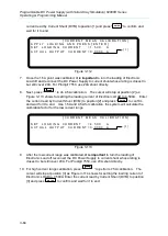
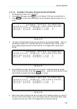
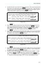
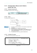
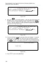
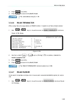
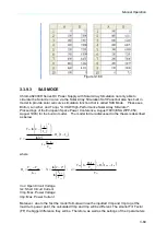
V O L T A G E C A L I B R A T I O N
]
R E M O V E E X T E R N A L L O A D A N D P R E S S[ E N T E R ]
S E T T I N G O U T P U T V O L T A G E 3 8 . 0 0
V
A C T U A L
O U T P U T V O L T A G E= 3 7 . 9 9 8 3 V
S E T T I N G O U T P U T V O L T A G E 1 3 2 . 0 0
V
A C T U A L
O U T P U T V O L T A G E= 1 3 1 .
V
[ 3 ]
[ 4 ]
9 9 9 1
Figure 3-139
9.
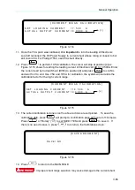
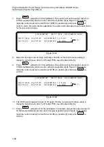
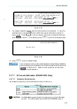
The voltage calibration is done when the above actions are completed. To save the
calibrated value, press
“
SAVE
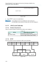
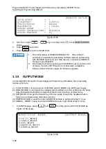
” and a confirmation screen will appear as shown in
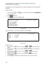
Figure 3-140. Press
“
1
” or turn the “Rotary” (
) knob to set SAVE=YES and
press
“
ENTER
” to save it. If not saving it, press “
EXIT
” to return to Calibration page.
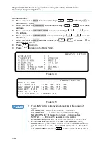
[ S A V E A R G U M E N T ]
S A V E = N O
Figure 3-140
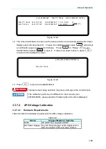
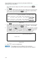
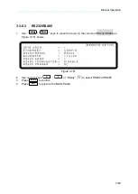
10. Press
“
EXIT
” to return to MAIN PAGE.
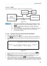
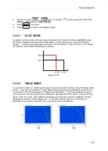
It is necessary to remove the output load when doing voltage calibration.
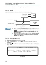
When performing the calibration, the VFD front panel will prompt the text
as shown in Figure 3-137. Make sure the output has no load, press
“
ENTER
” to start calibration.
3.3.7.7 IV Current Calibration (62020H-150S Only)
3.3.7.7.1
Hardware Requirements
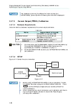
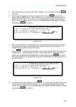
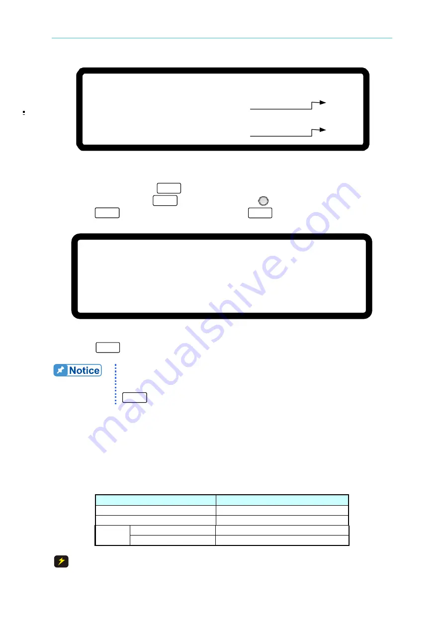
The hardware required for current calibration is shown in Table 3-12.
Table 3-12
Device
Suggest Model or Capacity
DVM
HP 34401A or equivalent DVM
DCCT
ULTRASTAB SATURN
LOAD
ELECTRICAL LOAD
CHROMA 63204 or equivalent
BREAKER
Capable current>=100A
CAUTION
The BREAKER capacity listed in the table above is for 62150H-600S
use only. For other models, see the OUTPUT CURRENT spec in

