Installation
2-7
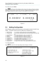
V = 6 0. 0 0 V I = 1 0. 0 0 _ A O F F
0 . 0 0 0 0 V 0 . 0 0 0 0 A
S E N S E F A U L T 0 . 0 W
S H U T
–
D N
Figure 2-8
2.4.2
Reverse Connection of Remote Sensing Wire
Polarity
The polarity of remote sensing wire must be connected correctl
y, that is the “+” terminal is
connected to the “+” of output terminal or to the connecting wire of the terminal, while the “–”
terminal is connected to the “–” of output terminal or to the connecting wire of the terminal.
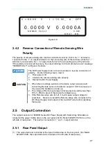
If the polarity is connected reversely, the output will drop to 0V and prompt an error message
“SENSE FAULT” as Figure 2-8 shows.
The DC Power Supply does not burn down due to reverse connection of
polarity. Do the following step to reset it:
1.
First power it off.
2.
Connect the remote sensing wire properly.
3.
Restart the DC Power Supply.
CAUTION
1. When there is voltage existed on the device output, please avoid
connecting Remote sense to the device output or UUT reversely as it
may cause the hardware to blow up.
2. The voltage of Remote sensing and local output should be less than
10% V_MAX to prevent the device from blowing up.
3. If the Remote sense wire fell off, it could cause output voltage to
overshoot. Be sure to install the Remote sense wire correctly to the
DC Power Supply local output or the load UUT side before operating
the device.
2.5
Output Connection
The output connector of 62000H Series DC Power Supply with Solar Array Simulation is
located at the upper middle area on the rear panel and for Model 62020H-150S it is on the
left side of rear panel. The
load is connected to “+” and “–” output terminal.
2.5.1
Rear Panel Output
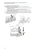
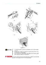
(1) The output terminal is located at the upper middle area on the rear panel. (For Model
62020H-150S, the output terminal is located on the left side of rear panel.)


