Manual Operation
3-23
2.
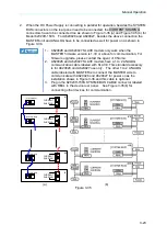
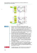
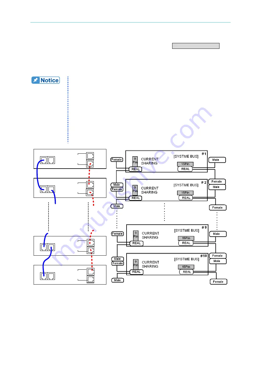
When the DC Power Supply is connecting in parallel for operation, besides the SYSTEM
BUS connectors on the rear panel need to be connected, the CURRENT SHARING
connectors have to be connected too as shown in Figure 3-35 (a) and Figure 3-35 (b) for
Model 62020H-150S. For A620028 and A620027, besides the above connection the
MASTER unit and ANALOG have to be connected as well for power on as shown in
Figure 3-36.
1.
A620028 and A620027 SLAVE models only work when the
MASTER firmware version is 1.30 or above for communication. For
firmware upgrade, please contact the agent of Chroma.
2.
A620028 and A620027 SLAVE models have a 1 to 2 ANALOG
communication cable labeled with SLAVE. This standard accessory
is for A620028 and A620027 use only. The other 1 to 2 ANALOG
cable labeled with MASTER is to connect the MASTER side to
communicate with A620028 and A620027 for power on as the
installation shows in Figure 3-36 and this cable is optional.
3.
Plug in the 62020H-150S SYSTME BUS CABLE connector labeled
with REAL to the device rear panel. See Figure 3-35(b) for
connecting other devices for communication.
CURRENT
SHARING
CURRENT
SHARING
CURRENT
SHARING
CURRENT
SHARING
1
#
2
#
10
#
9
#
[ SYSTEM BUS ]
[ SYSTEM BUS]
[ SYSTEM BUS]
[ SYSTEM BUS]
(a) (b)
Figure 3-35

