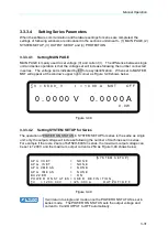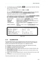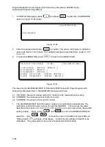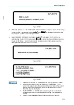
Manual Operation
3-45
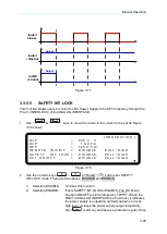
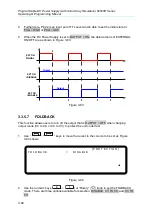
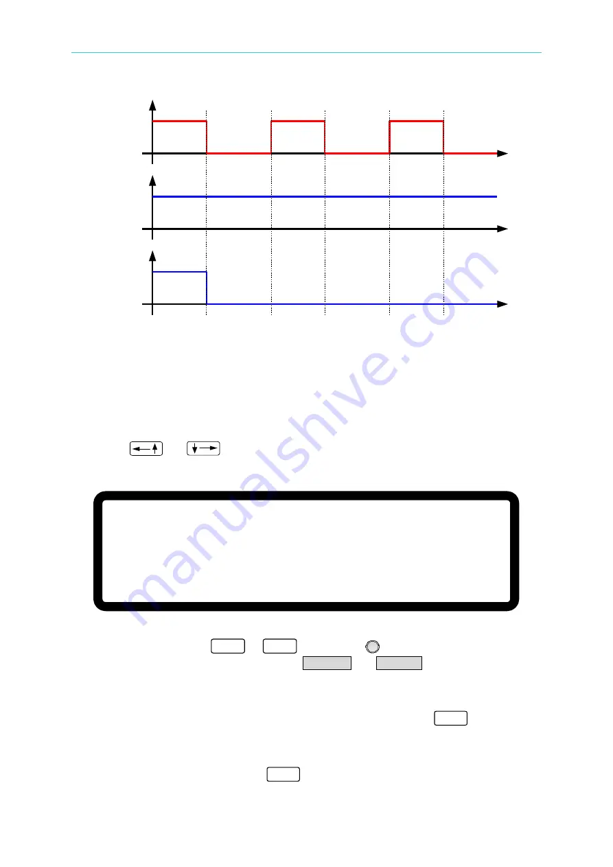
_INHIBIT
SIGNAL
INHIBIT
=DISABLE
INHIBIT
=ENABLE
Output
Output
Figure 3-77
3.3.5.5
SAFETY INT.LOCK
This function allows users to control the DC Power Supply to be OFF temporary through the
Pin 21 (INTERLOCK) of the ANALOG INTERFACE.
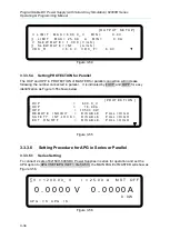
1.
Use “
” & “
” keys to move the cursor to the column to be set as Figure
3-78 shows.
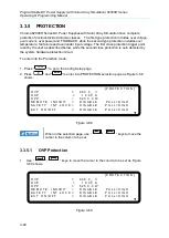
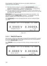
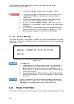
[ P R O T E C T I O N ]
O V P
= 6 0 0 . 0 V
O C P
= 1 8 . 9 0 A
O P P
= 5 2 5 0 . 0 W
R E M O T E I N H I B I T
= D I S A B L E P U L L = H I G H
S A F E
T Y I N T . L O C K
= D I S A B L E _ P U L L = H I G H
E X T O N / O F F = D I S A B L E P U L L = H I G H
▼
Figure 3-78
2.
Use the numeric keys
0
~
1
or
“Rotary” (
) knob to set SAFETY
INT.LOCK mode. There are two options, DISABLE and ENABLE.
1.
Selecting DISABLE:
It closes this function.
2.
Selecting ENABLE:
It sets SAFETY INT.LOCK to ENABLE. The DC Power
Supply’s ON/OFF is still controlled by “
OUTPUT
”. When the
PIN21 of ANALOG INTERFACE is at low level, it indicates
the power supply is outputting normally and when it is at
high level, it closes the power supply output temporarily
(
the “
ON/OFF
” is still on) and issues a protection signal. Once

