Verification
7-5
7.3.2 CR Mode Verification
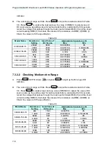
This test verifies if the resistance programming is within specifications when the module is
operating in the CR mode. The programmed resistance is calculated from the voltage divided
by current. The voltage (DMM (V)) passes through the module’s input terminal or
measurement terminal. The voltage (DMM (I)) passes through the current shunt, shunt
current = DMM (I) voltage/shunt resistor. If the voltage output and/or current limit in the DC
source are/is wrongly set, the load module protection circuit of OPP or OCP may be triggered.
Press
to close the warning screen and reset the resistance.
The Electronic Load modules implement constant resistance mode using CC circuits to
regulate the input. The input voltage of the load is regarded as reference for current control.
The formula is I/V = 1/R.
V:
input voltage as reference of D/A.
I:
controlled parameter to determine the resistance.
1/R:
conductance, reciprocal of resistance.
The specifications of CR mode accuracy are specified as conductance. The effect on the
programmed resistance value is not linear over the resistance range, because the resistance
is a reciprocal conductance. The electronic load is designed for high current applications of
CR mode. Therefore, when large resistance is required, reading the voltage and current from
the load, calculating the actual resistance, and adjusting the set value can improve accuracy.
To calculate the accuracy of programmed value error, the programmed value must be
reciprocated first. The error is then applied to the programmed value (conductance), and the
result is once again reciprocated. The following example illustrates the worst case of error in
CR mode.
Example 1: 0.133
Ω to 270Ω range (Model 63630-600-15, CRL)
The accuracy for this range is specified as 0.1% + 0.02S,
If 0.1
Ω is programmed, the actual resistance will be
Conductance: 10+(10
×
0.1%+0.02)
to 10
−
(10
×
0.1%+0.02)
Resistance:
0.0997
Ω
to 0.1003
Ω
If 0.05
Ω is programmed, the actual resistance will be
Conductance:
20+(20
×
0.1%+0.02)
to
20
−
(20
×
0.1%+0.02)
=
20.04S
to
19.96S
Resistance:
0.0499
Ω
to
0.0501
Ω
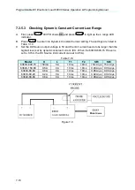
Connect the load module, DC source, DMM, and current shunt as shown in Figure 7-3 . Use
DMM (V) to measure the voltage passing through the module’s input terminal and the DMM
(I) that passes through the shunt resistor measurement port. Be careful in making
connections so that the contact resistance voltage drop will not affect the readings, or use
remote sensing to sense the UUT voltage. Load resistance = DMM (V)/shunt current.
7.3.2.1 Checking High ohm Range
A. Press
till VFD shows
CR
and press
to light up the H range LED
ENTER
MODE
RANGE
Summary of Contents for 63600 Series
Page 1: ......
Page 2: ......
Page 8: ...vi...
Page 9: ...vii...
Page 10: ...viii...
Page 16: ......
Page 40: ......
Page 110: ...Programmable DC Electronic Load 63600 Series Operation Programming Manual 4 34...
Page 132: ......
Page 252: ......


