Local Operation
3-99
PHASE C
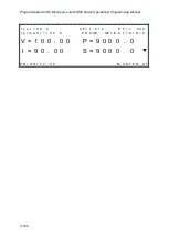
C phase Master (C1) unit display
I s e t = 9 0 . 0 C F = 1 . 4 1 4 P F = 1 . 0 0 0
I p ( m a X ) = 1 3 5 . 0
V = 1 0 0 . 0 0 P = 9 0 0 0 . 0
I = 9 0 . 0 0 S = 9 0 0 0 0
P R I O R I T Y : C F M A S T E R C 1
C phase SLAVE (C2) unit display
S L A V E C 2
When the TOTAL UNIT setting on the Master unit is inconsistent with what is detected by the
AC Load, the following display will be shown. At the same time, the AC Load loading will be
turned off.
I N C O R R E C T D E V I C E N U M B E R ! !
P L E A S E C H E C K I T A G A I N !
P R E S S < E N T E R > T O E X I T .
After the AC Load has been set up in parallel mode, it will be saved in the memory (ROM).
The AC Load will then start up in parallel mode on subsequent power on. Upon power on, the
Master unit will request to check the parallel connection as shown below.


