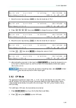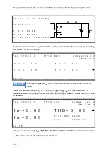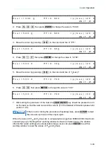
Programmable AC/DC Electronic Load 63800 Series Operation & Programming Manual
3-34
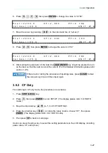
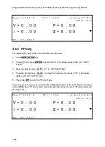
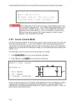
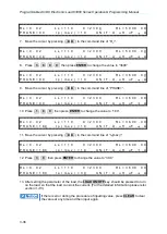
S e t t i n g E r r o r ! !
P l e a s e c h e c k t h e s e t t i n g
v a l u e s : P s e t a n d I p ( m a x ) .
If the setting value of of P
set
and I
p
(max) are unreasonable range then the
AC load will not load the UUT. For example, when voltage is 50V
rms
and
users set P
set
=1000W, I
p
(max) = 10A
rms
. If P
set
=1000W, the reasonable
loading current should be 20A
rms
. Thus, for the setting of I
p
(max)=10A
rms
the AC load will not load the UUT, please adjust P
set
lower or I
p
(max)
higher to the reasonable range value.
3.9.3 Inrush Current Mode
The RLC load network (
) can test the inrush current output of UUT. First, input the
load network parameter (R
s
, L
s
, C, R
L
) and use DSP to control the initial loading position. It
can simulate the input angle during maximum inrush current output. I
p
(max) is the parameter
needed to be set as well for the subsequent loading. (For the detailed information please refer
section 3.4.7
For switching to Inrush Current mode, the procedures are as below:
1. Press
RLC/DC RECT
key to go into the Rectified Load Mode.
2. Press
3
, then press
ENTER
to enter Inrush Current mode.
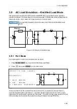
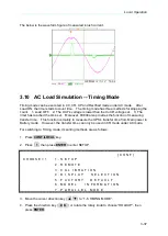
[ R E C T I F I E D L O A D ]
Rs
Ls
R
L
C
C H O O S E = 2
1 . R L C M O D E
2 . C P M O D E
3 . I N R U S H C U R R E N T
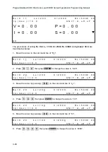
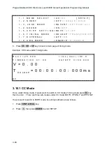
Users can press the arrow key to select the setting parameters on the LCD display, including
equivalent series resistance R
s
, equivalent series inductance L
s
, equivalent parallel load
capacitance C, equivalent parallel load resistance R
L
, phase in angle and I
p
(max). Users can
type the values with the Entry keys.
WARNING

