background image


Magic Box PS12 User Manual 3 

V1.4 

December 

2006 

1. Product 

overview


The Chroma-Q Magic Box PS12 supplies power and data to the Chroma-Q range of colour 
changers and compatible products (see below). A maximum capacity of 12PU (Power Units), it 
can be controlled remotely via ANSI E1.11 USITT DMX 512-A and delivers power and data via 3 
XLR4 outputs.  


2. Operation 

Power 

Connect power through a fused male IEC chassis connector with input power of 100 - 240V, 50-
60 Hz. The standard fuse is a 5x20mm 6A GMA 125V. It provides 3 circuits of 24VDC. 


Data 

Data input ANSI E1.11 USITT DMX 512-A from an external source or lighting control console 
connects through a male XLR-5. A pass through connection is available on the female XLR-5.  
Power and data outputs are from 3 individual female XLR-4 outputs to the colour changer units.  


Termination 

Data termination is built in at the input. 


Indicators 

The red LED indicates mains power is present and the green LED indicates a DMX signal is 
present. 


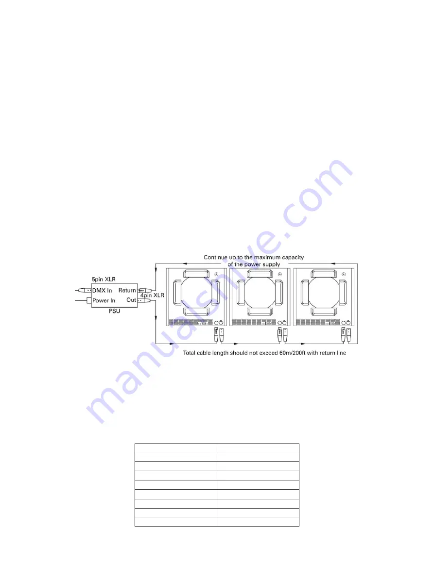
System Diagram 


The PS12 has been designed for cable loops of up to 60m/200ft per output. Closing the loop 

with a return cable will enhance the stability of the power delivered and connected to your data 
line. 


Load 

To simplify the choice of power supply we use the "PU" (Power Unit) to calculate the load 

requirements of the Chroma-Q system. The PS12 will supply up to 12 PU's, so you can plug-in 
12 Chroma-Q Plus (12 x 1PU = 12PU). The individual output has a maximum capacity of 8PU. 


Power Units 

Chroma-Q Product 

Power Unit 

Plus 1 

PU 

Broadway 1 

PU 

Cascade 1.5 

PU 

Universal 1.5 

PU 

M5 1.5 

PU 

M8 1.5 

PU 

Moving Mirror 

1 PU 

DMX Gobo Rotator 

0.6 PU 


Summary of Contents for Magic Box PS12

Page 1: ...Chroma Q Magic Box PS12 User Manual Version 1 4 December 2006 PN 134 0100 ...

Page 2: ...ion to devices and their functionality without notice due to our on going research and development The Chroma Q Magic Box PS12 has been designed specifically for the professional entertainment lighting industry Regular maintenance should be performed to ensure that the products perform well in the entertainment environment If you experience any difficulties with any Chroma Q products please contac...

Page 3: ... User Manual 2 V1 4 December 2006 Table of Contents 1 Product Overview 3 2 Operation 3 Power Data Termination Indicators System Diagram Load Power Units Installation Compatibility Control and Power Cables Accessories ...

Page 4: ... female XLR 5 Power and data outputs are from 3 individual female XLR 4 outputs to the colour changer units Termination Data termination is built in at the input Indicators The red LED indicates mains power is present and the green LED indicates a DMX signal is present System Diagram The PS12 has been designed for cable loops of up to 60m 200ft per output Closing the loop with a return cable will ...

Page 5: ...nd 3 supply ANSI E1 11 USITT DMX512 A control protocol with a ground drain wire to the connector shell Only genuine Tourflex Datasafe Cable is recommended for use of the Chroma Q colour changing system Damage will occur if the power connections short circuit to the data or ground shield connections When assembling XLR4 pin cables heat shrink sleeves should be used on each individual data pin and t...

Reviews: