background image

Chromalox 3901 User’s Manual

3

Section 2
Installation

Inspection &
Unpacking

On receipt of your 3901 controller, immediately make
note of any visible damage to the shipment packaging
and record this damage on the shipping documents.
Unpack the controller and carefully inspect it for
obvious damage due to shipment. If any damage has
occurred, YOU must file a claim with the transporter,
as they will not accept a claim from the shipper.

Storage

If the controller will not be immediately installed and
placed into operation, it should be stored in a cool, dry
environment in its original protective packaging until
time for installation and operation. Temperature
extremes and excessive moisture can damage the
instrument.

Installation
Steps

Installation of the 3901 controller requires 3 steps:

Step 1 - Accessing Internal Adjustments
Step 2 - Mounting
Step 3 - Wiring

Step 1
Accessing
Internal
Adjustments

The back cover of the 3901 can be easily removed to
access the following internal adjustment:

• Set Point Limit Potentiometer (page 11)

The page number referenced above describes this
internal adjustment. Although it is not necessary, it is
easier to make this adjustment prior to mounting
and wiring the controller
. If you want to establish a
Set Point Limit for your controller, read the page
referenced above before mounting and wiring the
3901.

Summary of Contents for 3901

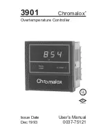
Page 1: ...Chromalox 3901 Chromalox Overtemperature Controller Issue Date Dec 1993 User s Manual 0037 75121 UL FM APPROVED ...

Page 2: ...cations 15 6 Warranty and Return Information 17 Illustrations Figure Topic Page 1 1 Overtemperature Control Application 1 1 2 Model Identification Table 2 2 1 Removing the Back Cover 4 2 2 Mounting Dimensions 4 2 3 Mounting Diagram 5 2 4 Wiring Connections 7 3 1 Front Panel Identification 10 3 2 Set Point Limit Potentiometer 12 4 1 Zero and Span Calibration Potentiometer 13 ...

Page 3: ...rates a typical overtem perature application Figure1 1 Overtemperature Control Application Chromalox READ TEMP ALARM HEAT SOURCE SHUTDOWN CONTACTOR 3901 F OVERTEMP FOR PROCESSOR HEATER SHEATH PROTECTOR Chromalox READ TEMP ALARM 3901 F FLOW SWITCH LEVEL CONTROL SHUTDOWN CONTACTOR AIR FLOW LEVEL SENSOR HEAT SOURCE OVERTEMP APPLIED WITH OTHER CUTOUT DEVICES Section 1 Introduction to the 3901 Controll...

Page 4: ...on Table Model Overtemperature Controller 3901 Digital Indicating UL Listed FM Approved Terminals for Remote Reset 1 4 DIN Panel Cutout 2 4 Inch Depth Behind Panel Code Control Output 1 Relay up to 230 Vac 20 amp resistive load SPST Latching Normally Energized Normally Open Contact Code Terminations 1 Barrier Strip with Screw Terminals Code Instrument Power 1 120 Vac 10 15 50 60 Hz 2 230 Vac 10 15...

Page 5: ...n its original protective packaging until time for installation and operation Temperature extremes and excessive moisture can damage the instrument Installation Steps Installation of the 3901 controller requires 3 steps Step 1 Accessing Internal Adjustments Step 2 Mounting Step 3 Wiring Step 1 Accessing Internal Adjustments The back cover of the 3901 can be easily removed to access the following i...

Page 6: ...eratures of 30 F to 130 F 0 C to 55 C Figure 2 2 gives the mounting dimensions for the controller Chromalox READ TEMP ALARM 3 8 96 3 8 96 2 4 61 8 19 3 6 92 3 5 89 PANEL CUTOUT Measurements are shown in inches Millimeters are shown in parenthesis Figure 2 2 Mounting Dimensions Figure 2 1 Removing the Back Cover WARNING TO REDUCE THE RISK OF FIRE OR ELECTRIC SHOCK PANEL MOUNT IN A CONTROLLED ENVIRO...

Page 7: ...crews on the two brackets Place the mounting tabs into the mounting holes located on the sides of the controller 3 From the rear of the controller tighten the screws until the brackets are tight against the panel securing the controller in the panel cutout 4 For other mounting configurations the mounting bracket tabs may be placed in the controller casing vent slots Figure 2 3 Mounting Diagram Mou...

Page 8: ...ng Practices when connecting this and any other controller 1 Do not run sensor leadwires and power leads together in the same conduit or wire tray 2 When planning the system wiring be sure to consider the importance of separating wiring into functionally similar bundles i e power leads sensor leads output signal lines etc If the power leads and sensor leads must cross they should cross at a 90 ang...

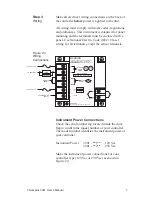
Page 9: ...ide the door flap to confirm the model number of your controller The model number identifies the instrument power of your controller Instrument Power 3901 1 120 Vac 3901 2 230 Vac Make the instrument power connections for your controller type 120 Vac or 230 Vac as shown in Figure 2 4 WARNING TO REDUCE THE RISK OF FIRE OR ELECTRIC SHOCK PANEL MOUNT IN A CONTROLLED ENVIRONMENT ENCLOSURE RELATIVELY F...

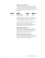
Page 10: ...one end only preferably at the case ground CASE GND of the controller If thermocouple extension wire is required it must be the same type of extension wire as the thermocouple for example if the thermocouple is Type J the extension wire must be Type J Alarm Output Connection The alarm relay output connections are made at terminals 1 and 2 Make the wiring connections as shown in Figure 2 4 using th...

Page 11: ...rating using the factory set alarm set point shown in the digital display The process temperature measured by the thermocouple can be selected for display by pushing the READ TEMP pushbutton The ALARM LED will be illuminated only if the process temperature is at or above the set point temperature or if the thermocouple is open The 3901 s front panel displays and indications and the RESET pushbutto...

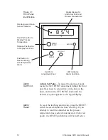
Page 12: ...lay for Alarm Set Point and Process Temperature Alarm Set Point Adjust Set Point To adjust the alarm set point locate the SET POINT adjustment behind the front door flap Insert a screwdriver in the hole in the knob and turn the SET POINT knob until the desired set point appears in the digital display Alarm Reset To reset the latching alarm relay press the RESET switch located behind the front door...

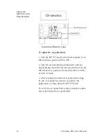
Page 13: ...process product or equipment The set point Limit is set at 100 of sensor span when shipped from the factory i e 1000 F for Type J thermocouples and 2000 F for Type K thermocouples An internal potentiometer allows you to adjust the set point limit from a range of 100 to 20 of sensor span To adjust the set point limit remove the back cover of the 3901 as described on page 4 Locate the set point limi...

Page 14: ... position FULL ON 2 Turn the set point limit potentiometer until the digital display reads the desired set point limit In the full clockwise position the set point limit is 100 or more of span 3 After reaching the desired set point limit setting be sure to readjust the process set point to the application s setting using the SET PT knob To verify the set point limit setting attempt to adjust the s...

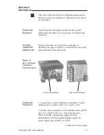
Page 15: ...over from the controller as described on page 4 Figure 4 1 identifies the zero and span calibration potentiometers Zero Potentiometer Span Potentiometer Calibration Procedure 1 Connect the sensor simulator to terminals 7 and 8 making sure to connect the to 7 and to 8 2 Set the sensor simulator to a minimum value 200 F for J T C 350 F for K T C While pressing the READ TEMP pushbutton adjust the zer...

Page 16: ...0 F for J T C 1600 F for K T C While pressing the READ TEMP pushbutton adjust the span potentiometer until the digital display equals the sensor input value 900 F or 1600 F 4 Repeat steps 2 and 3 as many times as necessary until both displays equal their respective sensor input values 5 Calibration complete ...

Page 17: ... operations Mechanical life 10 million operations Input Specifications Type J Thermocouple 0 to 999 F 0 to 500 C Type K Thermocouple 0 to 1999 F 0 to 1100 C Input Loop Resistance Up to 150 ohms Cold Junction Compensation Automatic typically less than 0 1 F per 1 F over ambient 50 to 120 F Indications Open Sensor Indications Red LED lamp for J thermocouple input 1 illuminates for K thermocouple inp...

Page 18: ... 92 mm x 92mm panel cutout Depth behind panel of 2 4 61 mm Projection at front of panel 0 8 20 mm Mounting Two screw in mounting brackets to secure controller in panel Influence of Line Voltage Variation Maximum change of 1 F for 10 nominal line voltage change Noise Rejection Common Mode Less than 2 F with 230 Vac 60 Hz applied from sensor input to instrument case Series Mode Less than 2 F with 10...

Page 19: ... Products must be installed and maintained in accordance with Chromalox instructions Users are responsible for the suitability of the products to their application There is no warranty against damage resulting from corrosion misapplication improper specification or other operating conditions beyond our control Claims against carriers for damage in transit must be filed by the buyer Returns Items r...

Page 20: ...Chromalox INSTRUMENTS AND CONTROLS 1382 HEIL QUAKER BOULEVARD LAVERGNE TN 37086 3536 PHONE 615 793 3900 FAX 615 793 3563 WIEGAND INDUSTRIAL DIVISION EMERSON ELECTRIC CO ...

Reviews: