Chromalox 3901 User’s Manual
7
Step 3
Wiring
Make all electrical wiring connections on the back of
the controller before power is applied to the unit.
All wiring must comply with local codes, regulations
and ordinances. This instrument is intended for panel
mounting and the terminals must be enclosed with a
panel. Use National Electric Code (NEC) Class 1
wiring for all terminals except the sensor terminals.
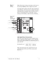
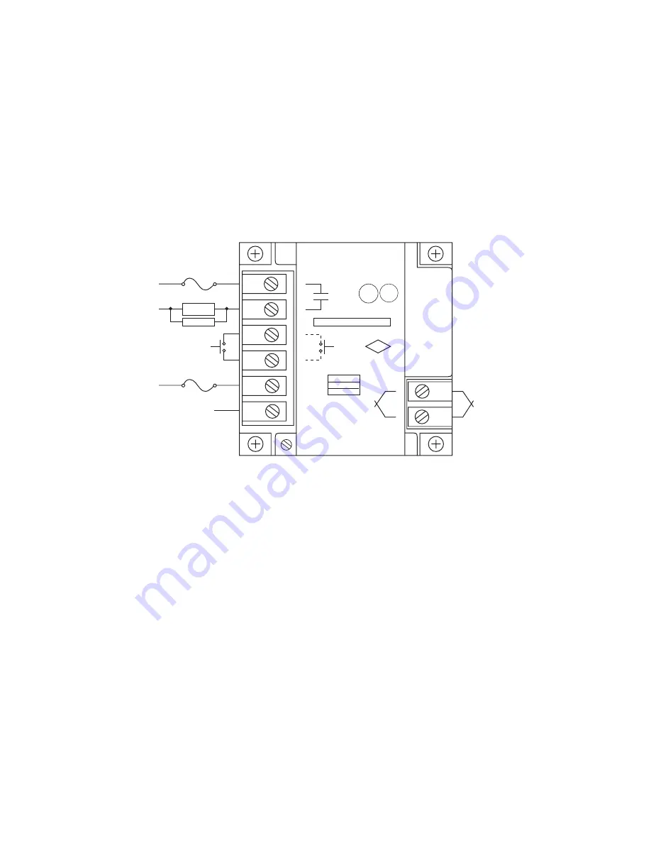
Figure 2.4
Wiring
Connections
Instrument Power Connections
Check the serial number tag located inside the door
flap to confirm the model number of your controller.
The model number identifies the instrument power of
your controller.
Instrument Power
3901 - **1**
120 Vac
3901 - **2**
230 Vac
Make the instrument power connections for your
controller type (120 Vac or 230 Vac) as shown in
Figure 2.4.
WARNING
TO REDUCE THE RISK OF FIRE OR ELECTRIC
SHOCK, PANEL MOUNT IN A CONTROLLED
ENVIRONMENT ENCLOSURE RELATIVELY FREE
OF CONTAMINANTS.
HAC
LAC/N
120 V AC
230 VAC
5 VA
1
2
3
4
5
6
CASE GND
7
8
+
REMOTE
RESET
INTERNAL
ALARM
RELAY
UL
®
LISTED
35MO
20A RES 55 C 120/230 VAC
RELAY RATING
FM
APPROVED
TC INPUT
NOTE: USE COPPER CONDUCTORS ONLY
REMOTE
RESET
AC COMMON OR
230 VAC
LOAD
SNUBBER
120 or 230 VAC
AC NEUTRAL
120 or 230 VAC
+

