background image

17

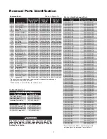
Renewal Parts Identification

Common Parts                                                       Shown in Figure 16

Item#

Description

Code CXHA-03, 

05, 07 & 10

Part No.

CXH-A-15, 

18 & 20

Part No.

CXH-A-25, 

30 & 35

Part No.

1

Panel wrapper

207-303891-001 207-303891-002 207-303891-003

6

Panel Bottom

207-303881-001 207-303881-002 207-303881-003

8

Panel Front

207-303883-001 207-303883-002 207-303883-003

9

Louver

182-303884-001 182-303884-002 182-303884-003

10

Washer Shoulder

328-302074-002 328-302074-002 328-302074-002

12

Spring

276-130368-001 276-130368-001 276-130368-001

14

Terminal Box Cover 080-302079-001 080-302079-001 080-302079-001

15

Screw 10-32

248-073662-002 248-073662-002 248-073662-002

16

Fan Blade

Consult Factory Consult Factory Consult Factory

17

Fan Guard

134-302063-004 134-302063-005 134-302063-006

25

Enclosure

347-304561-001 347-304561-001 347-304561-001

26

Bolt 3/8-16, 1.5 lg

345-075603-263 345-075603-263 345-075603-263

27

Washer flat

328-075528-085 328-075528-085 328-075528-085

28

Washer lock

328-075571-011 328-075571-011 328-075571-011

29

Hex Nut 3/8-16

200-075473-044 200-075473-044 200-075473-044

30

Plug conduit 1/2”

221-302180-001 221-302180-001 221-302180-001

31

Plug conduit 1”

221-302180-003 221-302180-003 221-302180-003

32

Union conduit 3/4” 354-302165-001 354-302165-001 354-302165-001

33

Union conduit 3/4” 354-302243-001 354-302243-001 354-302243-001

34

Conduit Box

Consult factory 069-304115-002 069-304115-002

35

Conduit 3/4”

Consult factory

Consult factory

Consult factory

44

Plug conduit 3/4”

221-302180-002 221-302180-002 221-302180-002

50

Bolt 5/16-18

345-075603-218 345-075603-218 345-075603-218

51

Washer

328-075571-010 328-075571-010 328-075571-010

52

Nut 5/16-18

200-075473-039 200-075473-039 200-075473-039

62

Cover Exp. Proof

080-042350-007 080-042350-007 080-042350-007

75

Conduit 3/4”

069-115087-049 069-115087-079 069-115087-093

**Have motor manufacturer and model number availiable when ordering a

  replacement motor (ATEX Certified).
***690V heaters - Contact factory for common parts

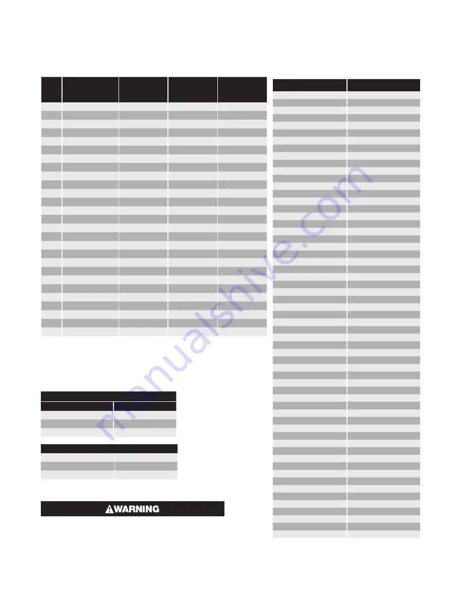
   Motor & Heat Exchanger Parts

Model

Heat Exchanger* Item 49

CXH-C-03S-81

353-305234-001

CXH-C-03S-83

353-305234-001

CXH-C-03S-21

353-305234-002

CXH-C-03S-23

353-305234-002

CXH-C-03S-33

353-305234-003

CXH-C-03S-403

353-305234-004

CXH-C-03S-53

353-305234-005

CXH-C-03S-43

353-305234-008

CXH-C-03S-63

353-305234-009

CXH-C-05S-81

353-305234-011

CXH-C-05S-83

353-305234-011

CXH-C-05S-21

353-305234-012

CXH-C-05S-23

353-305234-012

CXH-C-05S-33

353-305234-013

CXH-C-05S-403

353-305234-014

CXH-C-05S-53

353-305234-015

CXH-C-05S-43

353-305234-018

CXH-C-05S-63

353-305234-019

CXH-C-07S-81

353-305235-001

CXH-C-07S-83

353-305235-001

CXH-C-07S-21

353-305235-002

CXH-C-07S-23

353-305235-002

CXH-C-07S-33

353-305235-003

CXH-C-07S-403

353-305235-004

CXH-C-07S-53

353-305235-005

CXH-C-07S-43

353-305235-008

CXH-C-07S-63

353-305235-009

CXH-C-10S-83

353-305235-011

CXH-C-10S-21

353-305235-012

CXH-C-10S-23

353-305235-012

CXH-C-10S-43

353-305235-015

CXH-C-10S-63

353-305235-016

CXH-C-10M-33

353-305236-002

CXH-C-10M-403

353-305236-003

CXH-C-10M-53

353-305236-004

CXH-C-15M-83

353-305236-005

CXH-C-15M-23

353-305236-006

CXH-C-15M-33

353-305236-007

CXH-C-15M-403

353-305236-008

CXH-C-15M-53

353-305236-009

CXH-C-15M-43

353-305236-012

CXH-C-15M-63

353-305236-013

CXH-C-20M-33

353-305236-017

CXH-C-20M-403

353-305236-018

CXH-C-20M-53

353-305236-019

CXH-C-20M-43

353-305236-022

CXH-C-20M-63

353-305236-023

CXH-C-25L-33

353-305237-001

CXH-C-25L-403

353-305237-002

CXH-C-25L-53

353-305237-003

CXH-C-25L-43

353-305237-006

CXH-C-25L-63

353-305237-007

CXH-C-30L-33

353-305237-009

CXH-C-30L-403

353-305237-010

CXH-C-30L-53

353-305237-011

CXH-C-30L-43

353-305237-014

CXH-C-30L-63

353-305237-015

CXH-C-35L-43

353-305237-020

CXH-C-35L-63

353-305237-021

* For arctic duty conditions, heat exchanger with 

  ethylene glycol are required. Consult factory.

Optional Equipment

Optional Equipment Parts

Description

Part Number

Pilot Light (Amber)

213-121103-025

Pilot Light (Red)

213-121103-026

Insulation Fault Relay

072-305296-001

Mounting Kit Adapter

CXH-A-03S through 10S

027-302361-001

CXH-A-15M through 20M

027-302361-002

CXH-A-25L through 35L

027-302361-003

The factory must perform the replacement of the 

immersion heater or high temperature cutout. The 

heat exchanger seal must not be broken. Consult 

factory for service.

Summary of Contents for CXH-C-03S

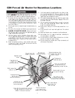
Page 1: ...1 PF490 CE AM 161 302421 006 March 2016 Installation and Operation Instructions CXH CE AM Forced Air Heater CXH Series Heaters for Hazardous Locations 0359 II 2 G EEx d IIB T3 ITS02ATEX1048 8 ...

Page 2: ...H C 10M 10 380 400 415V 3ph 50Hz 47 14 3 34 120 1450 2464 68 150 635 25 708 27 7 8 533 4 21 111 9 4 13 32 447 7 17 5 8 CXH C 15M 15 380 400 415V 3ph 50Hz 208 240 480 575V 3ph 60Hz 47 14 3 51 180 1450 2464 68 150 635 25 708 27 7 8 533 4 21 111 9 4 13 32 447 7 17 5 8 CXH C 20M 20 380 400 415V 3ph 50Hz 480 575V 3ph 60Hz 43 13 1 68 240 1450 2464 75 165 635 25 708 27 7 8 533 4 21 111 9 4 13 32 447 7 17...

Page 3: ...ature cutout 8 All unused threaded openings not used for supply wiring must be fitted with threaded plugs approved for use in hazardous locations 9 All unit electrical installation fittings conduit wiring and seals must meet applicable electric codes and local codes for hazardous locations 10 External line fusing or circuit breaker protection is re quired 11 Hi limit cutouts must never be bypassed...

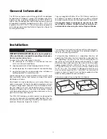
Page 4: ...nternal heat sources and away from heater discharge air streams Small rooms can be heated by one unit heater Where two walls are exposed the heater should be mounted as shown in Figure 2 Large rooms require multi unit installations Num ber and capacity of units will be determined by volume of building and square feet of floor area to be heated Arrange units to provide perimeter air circulation whe...

Page 5: ... to discharge freely Do not mount mercury type thermostat directly on unit vibra tion could cause malfunction Heater may be mounted on a shelf or stand from the bot tom e sure that mounting clearances are maintained and that bottom of unit has at least 1 clearance underneath it This is necessary for good air circulation and servicing of heat exchanger All mounting methods must allow for removal of...

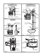
Page 6: ...2 Pole Base 3 8 ø Hardware Required for Mounting Cust Supplied 6 Ref 3 1 2 SCH 40 Pipe or 4 O D X 25 Wall Tube Cust Supplied Length to Suit P Adapter Bracket Supplied with 5 8 Bolts Single Point Swivel 4 ø Supplied Pole Support Bracket Heater Mounting Bracket Arm Hardware ø 3 8 Hardware Cust Supplied ø 1 2 x 4 U Bolts Hardware Cust Supplied Ceiling Mount Kit Model HMK 00 4 7 8 4 9 16 Swivel Ceilin...

Page 7: ...ed conduit openings must be fitted with plugs that are U L recognized for use in hazardous locations 6 Heaters may be provided with a built in control switch and or thermostat If not they should be controlled by an externally mounted disconnect switch and or separately mounted thermostat as shown in the appropriate wiring diagram on page 6 In case of malfunction the personnel in the area should be...

Page 8: ...rature cutout is also designed to shut down the unit completely if the fluid level is low or other heater malfunction occurs High Temperature cutout s must never be bypassed in the control circuit If the limit actuates shut down unit and investigate cause of abnormal operation Do not reenergize until the problem has been corrected Users should install adequate back up controls and safety devices w...

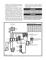
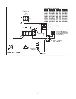
Page 9: ...e Pole on the Thermostat Remove this Wire when Using Thermostat T3 T2 T1 Optional Alarm Optional Elements Manual Reset High Limit Auto Reset High Limit Motor 1PH R Motor Contactor L2 L1 Red Fan Heat White Diagram II 1 PH Wiring with Fan Switch Transformer Color Code Tabulation PRI VOLT PRI XFMR LEAD CLRS 120V SEC LEAD CLRS 24V SEC LEAD CLRS H1 H2 X1 X2 X1 X2 208 BLK RED BLK WHT YEL BLU 240 BLK ORG...

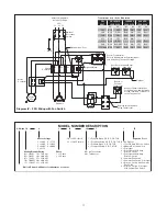
Page 10: ...losed Terminals of One Pole on the Thermostat Remove this Wire when Using Thermostat T3 T2 T1 Optional Alarm Optional Elements Manual Reset High Limit Auto Reset High Limit Motor 3PH Terminal Block Diagram III 3 PH Wiring Transformer Color Code Tabulation PRI VOLT PRI XFMR LEAD CLRS 120V SEC LEAD CLRS 24V SEC LEAD CLRS H1 H2 X1 X2 X1 X2 208 BLK RED BLK WHT YEL BLU 240 BLK ORG BLK WHT YEL BLU 380 B...

Page 11: ...U 380 BLK VIO BLK WHT YEL BLU 415 BLK YEL BLK WHT 415 BLK BRN YEL BLU 480 BLK BLK RED BLK WHT YEL BLU 575 600 BLK GRY BLK WHT YEL BLU Electric Blower Unit Heater for Hazardous Locations Heating Element Rating 03 3 0 kW 18 18 0 kW 05 5 0 kW 20 20 0 kW 07 7 5 kW 25 25 0 kW 10 10 0 kW 30 30 0 kW 15 15 0 kW 35 35 0 kW Heater Voltage 2 240V 6 575V 3 380V 8 208V 4 480V 9 600V 5 415V Phase 1 1 Phase 3 3 ...

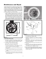
Page 12: ...tory supplied replacement blade only 6 Check for any sign of leaking from the heat exchanger Too little fluid will cause the high temperature cutout s to trip or cycle Periodically inspect the heater for leaks by visual examination using a flashlight Look for evidence of fluid dunning down the face of the heat exchanger from the top center Look for evidence of fluid inside the lower terminal enclo...

Page 13: ...tive it must be replaced with an origi nal factory supplied motor See renewal parts section 2 To replace the motor proceed as follows A Disconnect the unit from power supply B Remove the motor terminal box cover C Note wire connections for future reference and dis connect all wires from the motor terminals D Remove 4 bolts in the motor base holding it to the rear cabinet shelf E Remove 4 screws ho...

Page 14: ...ers or ser vicing heater Failure to comply could result in per sonal injury or property damage When provided the following components are located in the cast aluminum hazardous location enclosure Remove cover and retaining bolts to gain access the following items See Figure 15 1 CONTROL TRANSFORMER This item is located in the electrical enclosure It may be replaced while in the enclosure To servic...

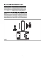
Page 15: ...makool PG Transformer Contactor Figure 15 Electrical Control Voltage 24 V 120 V 230 V Contactor 072 304551 002 072 304551 008 072 52560 011 Aux Contactor 072 304551 103 072 304551 103 Transformer 208 240 480 PRI 315 304252 002 315 304252 001 Transformer 380 415 PRI 315 304252 006 315 304252 007 Transformer 575 PRI 315 304252 005 315 304252 003 Transformer 690 PRI 315 304252 012 ...

Page 16: ...16 1 33 35 50 19 15 17 16 31 34 52 51 32 25 30 26 44 27 28 29 75 50 27 15 6 62 10 CO 8 12 9 49 15 Figure 16 ...

Page 17: ... CXH C 03S 81 353 305234 001 CXH C 03S 83 353 305234 001 CXH C 03S 21 353 305234 002 CXH C 03S 23 353 305234 002 CXH C 03S 33 353 305234 003 CXH C 03S 403 353 305234 004 CXH C 03S 53 353 305234 005 CXH C 03S 43 353 305234 008 CXH C 03S 63 353 305234 009 CXH C 05S 81 353 305234 011 CXH C 05S 83 353 305234 011 CXH C 05S 21 353 305234 012 CXH C 05S 23 353 305234 012 CXH C 05S 33 353 305234 013 CXH C ...

Page 18: ...e Chromalox limited warranty applicable to this product at http www chromalox com customer service policies termsofsale aspx 2016 Chromalox Inc All rights reserved Chromalox 103 Gamma Drive Pittsburgh PA 15238 412 967 3800 www chromalox com ...

Reviews: