background image

9

REMOTE FAN SWITCH

480V + Heaters require an additional fan relay. (Avail-

able as a kit or factory installed option and standard on 

heaters 20kW and above).

The wall switch is packed in the wiring compartment.
1.  Use 18 gauge (min.) NEC Class 1, 600V wiring that 

meets all Local and NEC requirements.

2.  Install the wall switch in a standard wall box in any 

convenient location that is protected from traffic or 

other accidental damage.

3.  Connect the field wire to the switch lead wires with 

suitable connectors.

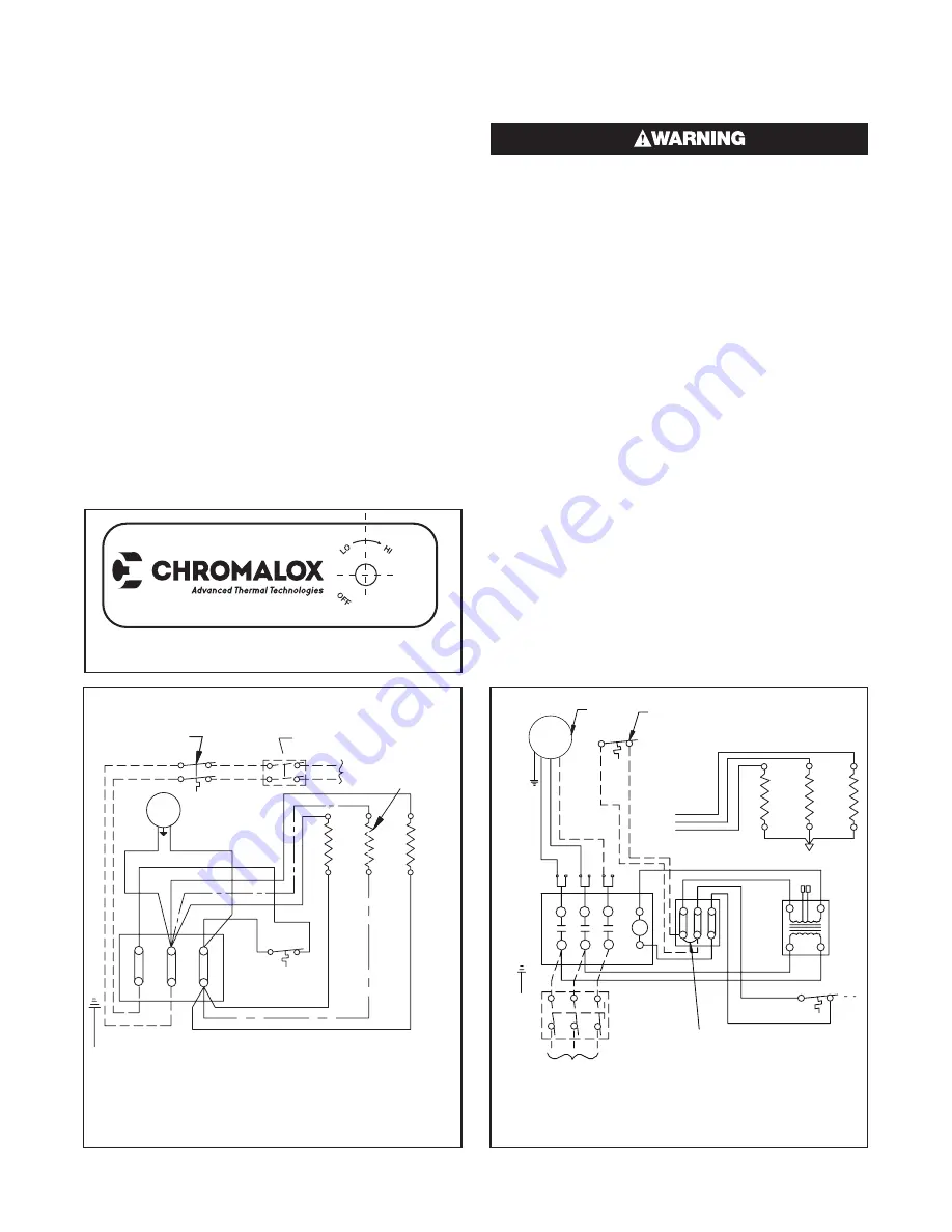
OPTIONAL THERMOSTAT (HVH-TK) Refer to In-

struction Sheet PF204.
Heaters can be equipped with an optional thermostat 

of the Bulb and Capillary type for automatic tempera-

ture control (Figure 8). The thermostat controls the 

heating elements and fan simultaneously to achieve 

set temperature.
The “Lo” setting of the thermostat is approximately 

40˚F, and the “Hi” setting is approximately 90˚F. 

Figure 9 — Thermostat Location, Front View

CONTROL VOLTAGE WIRING — EXTERNAL RE-

MOTE THERMOSTATS AND FAN SWITCHES

ELECTRIC SHOCK HAZARD. Be sure electricity 

is turned off at main switch first before wiring. 

Any installation involving electric heaters must 

be effectively grounded in accordance with the 

National Electrical Code to eliminate shock 

hazard.

1.  Use 600 volt, NEC Class 1 insulated wiring with a 

minimum gage of 18 for thermostats and minimum 

gauge of 14 for line voltage motor switch (remote 

fan switch without relay).

2.  The thermostat should be located in the area to be 

heated on an inside wall. The thermostat should 

not be exposed to drafts, sunlight, radiation from 

hot objects, or in a direct line with the discharge 

from the unit heater.

3.  Install the thermostat approximately 5 feet above 

the floor line.

4.  Install the remote fan switch in any convenient lo-

cation that is protected from traffic or likely acci-

dental damage.

5.  Internal optional controls are shown on the unit 

heater wiring diagrams by a dash line.

T1

T2

T3

L1

L2

L3

Terminal
Block

Cutout

Elements

1Ø Element wiring

(Omit for 2 element

heaters)

Optional disconnect switch

built-in or field installed

Power

60 Hz

Optional thermostat

built-in or field

installed

Blue

Blue

Motor

Cutout

NOTES:

1. Omit "L3" wiring for 1ø heaters

2. 3ø Motors used on all 480V, 7.5KV or higher

Remove jumper wire when

thermostat is used

Black

Red

Power 60 Hz

Pink

Optional

Disconnect

switch

built-in

or field

installed

T1

T2

T3

L1

L2

L3

Yellow

Blue

Sec

C1

C2

C3

3Ø Wiring

See Note #2

Optional Thermostat

Built-in or Field Installed

Motor

TO T1

TO T2

TO T3

Figure 10

Figure 11

Summary of Contents for HVH Series

Page 1: ...1 Installation Instructions Type HVH Horizontal Vertical Unit Heater PF505 10 161 305679 001 May 2019 ...

Page 2: ...2 ...

Page 3: ... heater is not intended for use in hazardous atmospheres where flammable vapors gases liquids or other combustible atmospheres are present as defined in the National Electric Code Failure to comply can result in explosion or fire For these applications see PDS CXH AEP PF490 ELECTRIC SHOCK HAZARD Disconnect all power before installing or servicing heater Failure to do so could result in personal in...

Page 4: ...208 10 000 3 27 8 34 130 20 5 8 17 1 8 12 3 4 30A 1 12 HVH 10 21 208 240 7 500 10 000 1 41 7 34 130 20 5 8 17 1 8 12 3 4 30A 1 12 HVH 10 23 208 240 7 500 10 000 3 24 0 34 130 20 5 8 17 1 8 12 3 4 30A 1 12 HVH 10 43 480 10 000 3 12 0 34 130 20 5 8 17 1 8 12 3 4 30A 1 13 HVH 12 83 208 12 500 3 34 8 42 663 20 5 8 17 1 8 12 3 4 50A 1 12 HVH 12 23 208 240 9 375 12 500 3 30 1 42 663 20 5 8 17 1 8 12 3 4...

Page 5: ...iling Refer to Table D for wall and ceiling clearances and Figure 2 for mounting spacing specifications KO FOR CONTROL WIRING KO FOR POWER WIRING TERMINAL BOX ACCESS DOOR Figure 4 Heater Back View Knockout Sizes HVH 02 05 1 2 3 4 1 HVH 07 20 1 2 1 1 HVH 25 50 1 1 4 2 1 Table C Rod Thread Type and Spacing Dimensions inches for Vertical Discharge Unit Rod Thread Type Dimensions In L1 L2 X 2 5 kW 3 8...

Page 6: ...al of 6 x 3 8 bolts The heater may be rotated to discharge in the desired direction Open and adjust louvers to desired position See Figure 5 and 6 for additional mounting details A B V N W C M U CL OF BOLT CEILING CEILING FOR SWIVEL MOUNTING TO CEILING USE ONE 5 8 LAG BOLT FOR FIXED MOUNTING TO CEILING USE FOUR 3 8 LAG BOLTS WALL W MINIMUM DISTANCE FROM WALL TO ALLOW FOR FULL 180 SWIVEL BACK OF HE...

Page 7: ...nd Wire on HVH 02 to HVH 20 and ground lug on HVH 25 to HVH 50 7 Terminals on contactor or on line voltage terminal block are supplied to be connected to accept the correct size power supply wire Copper rated at 600V and 60 C is satisfactory for the heater branch circuit 8 Electrical accessories either kits or factory in stalled options are shown connected by a dash line on the heater wiring diagr...

Page 8: ... louver to the desired position Top of Heater 45 Min All Louvers Figure 7 Louver Adjustment POWER DISCONNECT SWITCH Available as a kit or factory installed option This switch disconnects the power to the power leads when the handle is turned to its off position Refer to Instruc tion Sheet PF207 1 Use copper conductor supply wire only when con necting to the power line See Figure 8 2 Connection to ...

Page 9: ...ounded in accordance with the National Electrical Code to eliminate shock hazard 1 Use 600 volt NEC Class 1 insulated wiring with a minimum gage of 18 for thermostats and minimum gauge of 14 for line voltage motor switch remote fan switch without relay 2 The thermostat should be located in the area to be heated on an inside wall The thermostat should not be exposed to drafts sunlight radiation fro...

Page 10: ... jumper wire when thermostat is used Cutout Notes 1 Omit L3 wiring for 1ø heaters 2 3Ø motors used on all 480V 7 5Kw or higher heaters All other heaters use 1ø motors TO T2 TO T2 TO T2 TO T1 TO T1 TO T1 1Ø Wiring 3Ø Wiring Optional thermostat built in or field installed TO T1 TO T1 TO T2 TO T3 TO T3 TO T2 Motor L3 SEC See Note 2 Black Black Red Elements 3 Phase Wiring Optional Pliot Light Motor Co...

Page 11: ...ne Fusing Built in or External Disconnect Switch Capacitor Fusing Alternate 1PH Motor Wiring Fusing Figure 15 Elements 3 Phase Wiring Optional Pliot Light Motor Contactor AR Cutout Time Delay Relay Transformer 80VA Built In or Remote Thermostat Termnal Block Control Refer to Nameplate for XFMR Primary Input and Seconday Control Voltage Line Fusing Line Fusing Built in or External Disconnect Switch...

Page 12: ...tion 3 To operate the unit in the winter mode Fan Heat flip the toggle switch into the downward position Operating Integral Disconnect Switch 1 Chromalox HVH models equipped with an integral disconnect allow for power to be locally isolated from the heater 2 The disconnect switch used on HVH models is a rotary style disconnect designed for easy on off operation 3 To disconnect power from the HVH h...

Page 13: ...nstalled check to make sure it is switched to the Winter setting Check to make sure wires on switch are not reversed Element Failure Element failure can be confirmed by performing a continuity test or by measuring the elements resistance Unit turns off suddenly or cycles off before reaching temperature set point Low airflow is causing automatic reset temperature cutout on ele ments to activate The...

Page 14: ... 3 kW 04 4 0 k W 15 15 0 kW 40 37 5 kW 05 5 0 kW 20 19 8 kW 45 45 0 kW 07 7 5 kW 25 25 0 kW 50 50 0 kW 10 10 0 kW 30 30 0 kW Code Volts 2 240V A 220V 4 480V B 380V 6 600V C 400V 7 277V D 415V 8 208V Code Phase 1 1 3 3 Code Control 00 No Contactor 30 Contactor with 24V Transformer 31 Contactor with 24V Externally Supplied 32 Contactor with 120V Transformer 33 Contactor with 120V Externally Supplied...

Reviews: