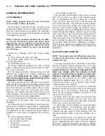
If there is any doubt about its condition, drain out a
sample for a double check.
SELECTION OF LUBRICANT
It is important that the proper lubricant be used in
these transmissions. Mopar ATF PLUS 3 (Automatic
Transmission Fluid- type 7176) should be used to aid
in ensuring optimum transmission performance. It is
important that the transmission fluid be maintained
at the prescribed level using the recommended fluids.
SPECIAL ADDITIVES
Chrysler Corporation does not recommend the
addition of any fluids to the transmission, other than
fluid listed above. An exception to this policy is the
use of special dyes to aid in detecting fluid leaks. The
use of transmission sealers should be avoided, since
they may adversely affect seals.
DESCRIPTION AND OPERATION
TORQUE CONVERTER CLUTCH
A torque converter clutch is standard on all vehi-
cles. The torque converter clutch is activated only in
direct drive and is controlled by the engine electron-
ics. A solenoid on the valve body, is powered by the
powertrain control module to activate torque con-
verter clutch.
HYDRAULIC CONTROL SYSTEM
The hydraulic control system makes the transaxle
fully automatic, and has four important functions to
perform. The components of any automatic control
system may be grouped into the following basic
groups:
The pressure supply system, the pressure regulat-
ing valves, the flow control valves, the clutches, and
band servos.
Taking each of these basic groups or systems in
turn, the control system may be described as follows:
PRESSURE SUPPLY SYSTEM
The pressure supply system consists of an oil pump
driven by the engine through the torque converter.
The single pump furnishes pressure for all the
hydraulic and lubrication requirements. Oil pump
housing assemblies are available with prese-
lected pump gears.
PRESSURE REGULATING VALVES
The pressure regulating valve controls line pres-
sure dependent on throttle opening. The governor
valve transmits regulated pressure to the valve body
(in conjunction with vehicle speed) to control upshift
and downshift.
The throttle valve transmits regulated pressure to
the transaxle (dependent on throttle position) to con-
trol upshift and downshift.
FLOW CONTROL VALVES
The manual valve provides the different transaxle
drive ranges as selected by the vehicle operator.
The 1-2 shift valve automatically shifts the tran-
saxle from first to second or from second to first,
depending on the vehicle operation.
The 2-3 shift valve automatically shifts the tran-
saxle from second to third or from third to second
depending on the vehicle operation.
The kickdown valve makes possible a forced down-
shift from third to second, second to first, or third to
first (depending on vehicle speed). This can be done
by depressing the accelerator pedal past the detent
feel near wide open throttle.
The shuttle valve has two separate functions and
performs each independently of the other. The first is
providing fast release of the kickdown band, and
smooth front clutch engagement when a lift-foot
upshift from second to third is made. The second
function is to regulate the application of the kick-
down servo and band when making third to second
kickdown.
The by-pass valve provides for smooth application
of the kickdown band on 1-2 upshifts.
The torque converter clutch solenoid allows for the
electronic control of the torque converter clutch. It
also disengages the torque converter at closed throt-
tle. This is done during engine warm-up, and part-
throttle acceleration.
The switch valve directs oil to apply the torque
converter clutch in one position. The switch valve
releases the torque converter clutch in the other posi-
tion.
CLUTCHES, BAND SERVOS, AND ACCUMULATOR
The front and rear clutch pistons, and both servo
pistons are moved hydraulically to engage the
clutches and apply the bands. The pistons are
released by spring tension when hydraulic pressure
is released. On the 2-3 upshift, the kickdown servo
piston is released by spring tension and hydraulic
pressure.
The accumulator controls the hydraulic pressure
on the apply side of the kickdown servo during the
1-2 upshift; thereby, cushioning the kickdown band
application at any throttle position.
NS
TRANSAXLE AND POWER TRANSFER UNIT
21 - 3
GENERAL INFORMATION (Continued)
Summary of Contents for 1998 Voyager
Page 8: ...FASTENER IDENTIFICATION NS INTRODUCTION 5 GENERAL INFORMATION Continued ...
Page 9: ...FASTENER STRENGTH 6 INTRODUCTION NS GENERAL INFORMATION Continued ...
Page 11: ...METRIC CONVERSION 8 INTRODUCTION NS GENERAL INFORMATION Continued ...
Page 12: ...TORQUE SPECIFICATIONS NS INTRODUCTION 9 GENERAL INFORMATION Continued ...
Page 16: ......
Page 26: ......
Page 93: ...RED BRAKE WARNING LAMP FUNCTION NS BRAKES 5 11 DIAGNOSIS AND TESTING Continued ...
Page 94: ...POWER BRAKE SYSTEM DIAGNOSTICS 5 12 BRAKES NS DIAGNOSIS AND TESTING Continued ...
Page 95: ...VEHICLE ROAD TEST BRAKE NOISE NS BRAKES 5 13 DIAGNOSIS AND TESTING Continued ...
Page 222: ...COOLING SYSTEM DIAGNOSIS 7 8 COOLING SYSTEM NS DIAGNOSIS AND TESTING Continued ...
Page 223: ...NS COOLING SYSTEM 7 9 DIAGNOSIS AND TESTING Continued ...
Page 224: ...7 10 COOLING SYSTEM NS DIAGNOSIS AND TESTING Continued ...
Page 225: ...NS COOLING SYSTEM 7 11 DIAGNOSIS AND TESTING Continued ...
Page 226: ...7 12 COOLING SYSTEM NS DIAGNOSIS AND TESTING Continued ...
Page 280: ......
Page 286: ......
Page 289: ...CHARGING SYSTEM SCHEMATIC TYPICAL NS CHARGING SYSTEM 8C 3 DIAGNOSIS AND TESTING Continued ...
Page 291: ...CHARGING SYSTEM TEST NS CHARGING SYSTEM 8C 5 DIAGNOSIS AND TESTING Continued ...
Page 292: ...OVERCHARGE TEST 8C 6 CHARGING SYSTEM NS DIAGNOSIS AND TESTING Continued ...
Page 294: ...VOLTAGE DROP TEST 8C 8 CHARGING SYSTEM NS ...
Page 298: ......
Page 372: ......
Page 377: ...NS GS INSTRUMENT PANEL AND SYSTEMS 8E 5 DIAGNOSIS AND TESTING Continued ...
Page 378: ...8E 6 INSTRUMENT PANEL AND SYSTEMS NS GS DIAGNOSIS AND TESTING Continued ...
Page 379: ...NS GS INSTRUMENT PANEL AND SYSTEMS 8E 7 DIAGNOSIS AND TESTING Continued ...
Page 380: ...8E 8 INSTRUMENT PANEL AND SYSTEMS NS GS DIAGNOSIS AND TESTING Continued ...
Page 381: ...NS GS INSTRUMENT PANEL AND SYSTEMS 8E 9 DIAGNOSIS AND TESTING Continued ...
Page 382: ...8E 10 INSTRUMENT PANEL AND SYSTEMS NS GS DIAGNOSIS AND TESTING Continued ...
Page 383: ...NS GS INSTRUMENT PANEL AND SYSTEMS 8E 11 DIAGNOSIS AND TESTING Continued ...
Page 384: ...8E 12 INSTRUMENT PANEL AND SYSTEMS NS GS DIAGNOSIS AND TESTING Continued ...
Page 385: ...NS GS INSTRUMENT PANEL AND SYSTEMS 8E 13 DIAGNOSIS AND TESTING Continued ...
Page 386: ...8E 14 INSTRUMENT PANEL AND SYSTEMS NS GS DIAGNOSIS AND TESTING Continued ...
Page 402: ......
Page 428: ......
Page 440: ......
Page 478: ......
Page 496: ......
Page 504: ......
Page 508: ......
Page 524: ......
Page 542: ......
Page 546: ......
Page 550: ......
Page 559: ...SPECIAL TOOLS SPECIAL TOOL Degausser 6029 NS OVERHEAD CONSOLE 8V 9 ...
Page 560: ......
Page 562: ......
Page 564: ...8W 01 2 8W 01 GENERAL INFORMATION NS GS DESCRIPTION AND OPERATION Continued ...
Page 565: ...NS GS 8W 01 GENERAL INFORMATION 8W 01 3 DESCRIPTION AND OPERATION Continued ...
Page 580: ......
Page 616: ......
Page 660: ......
Page 664: ......
Page 704: ......
Page 718: ......
Page 728: ......
Page 740: ......
Page 744: ......
Page 758: ......
Page 768: ......
Page 784: ......
Page 792: ......
Page 796: ......
Page 800: ......
Page 814: ......
Page 822: ......
Page 826: ......
Page 832: ......
Page 836: ......
Page 840: ......
Page 876: ......
Page 1024: ......
Page 1220: ...Fig 3 Lubrication Lines 9 42 ENGINE NS GS DESCRIPTION AND OPERATION Continued ...
Page 1224: ...ENGINE DIAGNOSIS MECHANICAL CONT 9 46 ENGINE NS GS DIAGNOSIS AND TESTING Continued ...
Page 1286: ...Fig 5 Front Crossmember Dimensions 13 6 FRAME AND BUMPERS NS SPECIFICATIONS Continued ...
Page 1287: ...Fig 6 Engine Compartment Top View NS FRAME AND BUMPERS 13 7 SPECIFICATIONS Continued ...
Page 1289: ...Fig 8 Full Vehicle Bottom View NS FRAME AND BUMPERS 13 9 SPECIFICATIONS Continued ...
Page 1291: ...Fig 11 Body Side Openings NS FRAME AND BUMPERS 13 11 SPECIFICATIONS Continued ...
Page 1292: ......
Page 1302: ...FUEL PRESSURE BELOW SPECIFICATIONS 14 8 FUEL SYSTEM NS DIAGNOSIS AND TESTING Continued ...
Page 1304: ...FUEL INJECTOR DIAGNOSIS 14 10 FUEL SYSTEM NS DIAGNOSIS AND TESTING Continued ...
Page 1368: ......
Page 1426: ......
Page 1472: ......
Page 1479: ...Diagnosis Guide NS TRANSAXLE AND POWER TRANSFER UNIT 21 5 DIAGNOSIS AND TESTING Continued ...
Page 1480: ...Diagnosis Guide 21 6 TRANSAXLE AND POWER TRANSFER UNIT NS DIAGNOSIS AND TESTING Continued ...
Page 1481: ...Diagnosis Guide NS TRANSAXLE AND POWER TRANSFER UNIT 21 7 DIAGNOSIS AND TESTING Continued ...
Page 1482: ...Diagnosis Guide 21 8 TRANSAXLE AND POWER TRANSFER UNIT NS DIAGNOSIS AND TESTING Continued ...
Page 1483: ...Diagnosis Guide NS TRANSAXLE AND POWER TRANSFER UNIT 21 9 DIAGNOSIS AND TESTING Continued ...
Page 1484: ...Diagnosis Guide 21 10 TRANSAXLE AND POWER TRANSFER UNIT NS DIAGNOSIS AND TESTING Continued ...
Page 1485: ...Diagnosis Guide NS TRANSAXLE AND POWER TRANSFER UNIT 21 11 DIAGNOSIS AND TESTING Continued ...
Page 1486: ...Diagnosis Guide 21 12 TRANSAXLE AND POWER TRANSFER UNIT NS DIAGNOSIS AND TESTING Continued ...
Page 1656: ......
Page 1723: ...LEAD CORRECTION CHART NS TIRES AND WHEELS 22 5 DIAGNOSIS AND TESTING Continued ...
Page 1726: ...SPECIFICATIONS TIRE SPECIFICATIONS 22 8 TIRES AND WHEELS NS ...
Page 1866: ......
Page 1904: ......
Page 1928: ......

