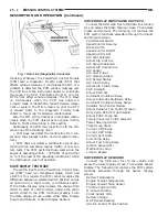
The primary components within the assembly are:
A three port solenoid that activates both of the func-
tions listed above; a pump which contains a switch,
two check valves and a spring/diaphragm, a canister
vent valve (CVV) seal which contains a spring loaded
vent seal valve.
Immediately after a cold start, between predeter-
mined temperature thresholds limits, the three port
solenoid is briefly energized. This initializes the
pump by drawing air into the pump cavity and also
closes the vent seal. During non test conditions the
vent seal is held open by the pump diaphragm
assembly which pushes it open at the full travel posi-
tion. The vent seal will remain closed while the
pump is cycling due to the reed switch triggering of
the three port solenoid that prevents the diaphragm
assembly from reaching full travel. After the brief
initialization period, the solenoid is de-energized
allowing atmospheric pressure to enter the pump
cavity, thus permitting the spring to drive the dia-
phragm which forces air out of the pump cavity and
into the vent system. When the solenoid is energized
and de energized, the cycle is repeated creating flow
in typical diaphragm pump fashion. The pump is con-
trolled in 2 modes:
Pump Mode: The pump is cycled at a fixed rate to
achieve a rapid pressure build in order to shorten the
overall test length.
Test Mode: The solenoid is energized with a fixed
duration pulse. Subsequent fixed pulses occur when
the diaphragm reaches the Switch closure point.
The spring in the pump is set so that the system
will achieve an equalized pressure of about 7.5” H20.
The cycle rate of pump strokes is quite rapid as the
system begins to pump up to this pressure. As the
pressure increases, the cycle rate starts to drop off. If
there is no leak in the system, the pump would even-
tually stop pumping at the equalized pressure. If
there is a leak, it will continue to pump at a rate rep-
resentative of the flow characteristic of the size of the
leak. From this information we can determine if the
leak is larger than the required detection limit (cur-
rently set at .020” orifice by CARB). If a leak is
revealed during the leak test portion of the test, the
test is terminated at the end of the test mode and no
further system checks will be performed.
After passing the leak detection phase of the test,
system pressure is maintained by turning on the
LDP’s solenoid until the purge system is activated.
Purge activation in effect creates a leak. The cycle
rate is again interrogated and when it increases due
to the flow through the purge system, the leak check
portion of the diagnostic is complete.
The canister vent valve will unseal the system
after completion of the test sequence as the pump
diaphragm assembly moves to the full travel position.
Evaporative system functionality will be verified by
using the stricter evap purge flow monitor. At an
appropriate warm idle the LDP will be energized to
seal the canister vent. The purge flow will be clocked
up from some small value in an attempt to see a
shift in the 02 control system. If fuel vapor, indicated
by a shift in the 02 control, is present the test is
passed. If not, it is assumed that the purge system is
not functioning in some respect. The LDP is again
turned off and the test is ended.
TRIP DEFINITION
A “Trip” means vehicle operation (following an
engine-off period) of duration and driving mode such
that all components and systems are monitored at
least once by the diagnostic system. The monitors
must successfully pass before the PCM can verify
that a previously malfunctioning component is meet-
ing the normal operating conditions of that compo-
nent. For misfire or fuel system malfunction, the
MIL may be extinguished if the fault does not recur
when monitored during three subsequent sequential
driving cycles in which conditions are similar to
those under which the malfunction was first deter-
mined.
Anytime the MIL is illuminated, a DTC is stored.
The DTC can self erase only when the MIL has been
extinguished. Once the MIL is extinguished, the
PCM must pass the diagnostic test for the most
recent DTC for 40 warm-up cycles (80 warm-up
cycles for the Fuel System Monitor and the Misfire
Monitor). A warm-up cycle can best be described by
the following:
•
The engine must be running
•
A rise of 40°F in engine temperature must occur
from the time when the engine was started
•
Engine coolant temperature must reach at least
160°F
•
A “driving cycle” that consists of engine start up
and engine shut off.
Once the above conditions occur, the PCM is con-
sidered to have passed a warm-up cycle. Due to the
conditions required to extinguish the MIL and erase
the DTC, it is most important that after a repair has
been made, all DTC’s be erased and the repair veri-
fied.
COMPONENT MONITORS
There are several components that will affect vehi-
cle emissions if they malfunction. If one of these com-
ponents
malfunctions
the
Malfunction
Indicator
Lamp (Check Engine) will illuminate.
Some of the component monitors are checking for
proper operation of the part. Electrically operated
25 - 10
EMISSION CONTROL SYSTEMS
NS
DESCRIPTION AND OPERATION (Continued)
Summary of Contents for 1998 Voyager
Page 8: ...FASTENER IDENTIFICATION NS INTRODUCTION 5 GENERAL INFORMATION Continued ...
Page 9: ...FASTENER STRENGTH 6 INTRODUCTION NS GENERAL INFORMATION Continued ...
Page 11: ...METRIC CONVERSION 8 INTRODUCTION NS GENERAL INFORMATION Continued ...
Page 12: ...TORQUE SPECIFICATIONS NS INTRODUCTION 9 GENERAL INFORMATION Continued ...
Page 16: ......
Page 26: ......
Page 93: ...RED BRAKE WARNING LAMP FUNCTION NS BRAKES 5 11 DIAGNOSIS AND TESTING Continued ...
Page 94: ...POWER BRAKE SYSTEM DIAGNOSTICS 5 12 BRAKES NS DIAGNOSIS AND TESTING Continued ...
Page 95: ...VEHICLE ROAD TEST BRAKE NOISE NS BRAKES 5 13 DIAGNOSIS AND TESTING Continued ...
Page 222: ...COOLING SYSTEM DIAGNOSIS 7 8 COOLING SYSTEM NS DIAGNOSIS AND TESTING Continued ...
Page 223: ...NS COOLING SYSTEM 7 9 DIAGNOSIS AND TESTING Continued ...
Page 224: ...7 10 COOLING SYSTEM NS DIAGNOSIS AND TESTING Continued ...
Page 225: ...NS COOLING SYSTEM 7 11 DIAGNOSIS AND TESTING Continued ...
Page 226: ...7 12 COOLING SYSTEM NS DIAGNOSIS AND TESTING Continued ...
Page 280: ......
Page 286: ......
Page 289: ...CHARGING SYSTEM SCHEMATIC TYPICAL NS CHARGING SYSTEM 8C 3 DIAGNOSIS AND TESTING Continued ...
Page 291: ...CHARGING SYSTEM TEST NS CHARGING SYSTEM 8C 5 DIAGNOSIS AND TESTING Continued ...
Page 292: ...OVERCHARGE TEST 8C 6 CHARGING SYSTEM NS DIAGNOSIS AND TESTING Continued ...
Page 294: ...VOLTAGE DROP TEST 8C 8 CHARGING SYSTEM NS ...
Page 298: ......
Page 372: ......
Page 377: ...NS GS INSTRUMENT PANEL AND SYSTEMS 8E 5 DIAGNOSIS AND TESTING Continued ...
Page 378: ...8E 6 INSTRUMENT PANEL AND SYSTEMS NS GS DIAGNOSIS AND TESTING Continued ...
Page 379: ...NS GS INSTRUMENT PANEL AND SYSTEMS 8E 7 DIAGNOSIS AND TESTING Continued ...
Page 380: ...8E 8 INSTRUMENT PANEL AND SYSTEMS NS GS DIAGNOSIS AND TESTING Continued ...
Page 381: ...NS GS INSTRUMENT PANEL AND SYSTEMS 8E 9 DIAGNOSIS AND TESTING Continued ...
Page 382: ...8E 10 INSTRUMENT PANEL AND SYSTEMS NS GS DIAGNOSIS AND TESTING Continued ...
Page 383: ...NS GS INSTRUMENT PANEL AND SYSTEMS 8E 11 DIAGNOSIS AND TESTING Continued ...
Page 384: ...8E 12 INSTRUMENT PANEL AND SYSTEMS NS GS DIAGNOSIS AND TESTING Continued ...
Page 385: ...NS GS INSTRUMENT PANEL AND SYSTEMS 8E 13 DIAGNOSIS AND TESTING Continued ...
Page 386: ...8E 14 INSTRUMENT PANEL AND SYSTEMS NS GS DIAGNOSIS AND TESTING Continued ...
Page 402: ......
Page 428: ......
Page 440: ......
Page 478: ......
Page 496: ......
Page 504: ......
Page 508: ......
Page 524: ......
Page 542: ......
Page 546: ......
Page 550: ......
Page 559: ...SPECIAL TOOLS SPECIAL TOOL Degausser 6029 NS OVERHEAD CONSOLE 8V 9 ...
Page 560: ......
Page 562: ......
Page 564: ...8W 01 2 8W 01 GENERAL INFORMATION NS GS DESCRIPTION AND OPERATION Continued ...
Page 565: ...NS GS 8W 01 GENERAL INFORMATION 8W 01 3 DESCRIPTION AND OPERATION Continued ...
Page 580: ......
Page 616: ......
Page 660: ......
Page 664: ......
Page 704: ......
Page 718: ......
Page 728: ......
Page 740: ......
Page 744: ......
Page 758: ......
Page 768: ......
Page 784: ......
Page 792: ......
Page 796: ......
Page 800: ......
Page 814: ......
Page 822: ......
Page 826: ......
Page 832: ......
Page 836: ......
Page 840: ......
Page 876: ......
Page 1024: ......
Page 1220: ...Fig 3 Lubrication Lines 9 42 ENGINE NS GS DESCRIPTION AND OPERATION Continued ...
Page 1224: ...ENGINE DIAGNOSIS MECHANICAL CONT 9 46 ENGINE NS GS DIAGNOSIS AND TESTING Continued ...
Page 1286: ...Fig 5 Front Crossmember Dimensions 13 6 FRAME AND BUMPERS NS SPECIFICATIONS Continued ...
Page 1287: ...Fig 6 Engine Compartment Top View NS FRAME AND BUMPERS 13 7 SPECIFICATIONS Continued ...
Page 1289: ...Fig 8 Full Vehicle Bottom View NS FRAME AND BUMPERS 13 9 SPECIFICATIONS Continued ...
Page 1291: ...Fig 11 Body Side Openings NS FRAME AND BUMPERS 13 11 SPECIFICATIONS Continued ...
Page 1292: ......
Page 1302: ...FUEL PRESSURE BELOW SPECIFICATIONS 14 8 FUEL SYSTEM NS DIAGNOSIS AND TESTING Continued ...
Page 1304: ...FUEL INJECTOR DIAGNOSIS 14 10 FUEL SYSTEM NS DIAGNOSIS AND TESTING Continued ...
Page 1368: ......
Page 1426: ......
Page 1472: ......
Page 1479: ...Diagnosis Guide NS TRANSAXLE AND POWER TRANSFER UNIT 21 5 DIAGNOSIS AND TESTING Continued ...
Page 1480: ...Diagnosis Guide 21 6 TRANSAXLE AND POWER TRANSFER UNIT NS DIAGNOSIS AND TESTING Continued ...
Page 1481: ...Diagnosis Guide NS TRANSAXLE AND POWER TRANSFER UNIT 21 7 DIAGNOSIS AND TESTING Continued ...
Page 1482: ...Diagnosis Guide 21 8 TRANSAXLE AND POWER TRANSFER UNIT NS DIAGNOSIS AND TESTING Continued ...
Page 1483: ...Diagnosis Guide NS TRANSAXLE AND POWER TRANSFER UNIT 21 9 DIAGNOSIS AND TESTING Continued ...
Page 1484: ...Diagnosis Guide 21 10 TRANSAXLE AND POWER TRANSFER UNIT NS DIAGNOSIS AND TESTING Continued ...
Page 1485: ...Diagnosis Guide NS TRANSAXLE AND POWER TRANSFER UNIT 21 11 DIAGNOSIS AND TESTING Continued ...
Page 1486: ...Diagnosis Guide 21 12 TRANSAXLE AND POWER TRANSFER UNIT NS DIAGNOSIS AND TESTING Continued ...
Page 1656: ......
Page 1723: ...LEAD CORRECTION CHART NS TIRES AND WHEELS 22 5 DIAGNOSIS AND TESTING Continued ...
Page 1726: ...SPECIFICATIONS TIRE SPECIFICATIONS 22 8 TIRES AND WHEELS NS ...
Page 1866: ......
Page 1904: ......
Page 1928: ......


