ulated shop air to the metal back- pressure fitting on
the EGR valve.
(6) By hand, open the throttle to the wide open
position. Air SHOULD NOT BE HEARD emitting
from the intake manifold while applying air pressure
at the back-pressure fitting.
(7) If air CAN BE HEARD emitting from the
intake manifold, the poppet valve (Fig. 4) is leaking
at the bottom of the EGR valve. Replace the EGR
valve. Note: The EGR valve, valve control and
attaching hoses are serviced as one assembly. Refer
to EGR Valve Removal/Installation in this group. Do
not attempt clean the old EGR valve.
EGR VALVE CONTROL (TRANSDUCER) TEST
TESTING ELECTRICAL SOLENOID PORTION
OF VALVE
This is not to be used as a complete test of the
EGR system.
Electrical operation of the valve should be checked
with the DRB scan tool. Refer to the appropriate
Powertrain Diagnostic Procedures service manual for
operation of the DRB scan tool. Replace solenoid if
necessary, unit serviced only as an assembly.
TESTING VACUUM TRANSDUCER PORTION
OF VALVE
The first part of this test will determine if the
transducer diaphragm at the back-pressure side of
the valve has ruptured or is leaking. The second part
of the test will determine if engine vacuum (full-man-
ifold) is flowing from the inlet to the outlet side of
the valve. This is not to be used as a complete test of
the EGR system.
(1) Disconnect the rubber back-pressure hose from
the fitting at the bottom of EGR valve (Fig. 4).
(2) Connect a hand-held vacuum pump to this fit-
ting.
(3) Apply 10 inches of vacuum to this fitting.
(4) If vacuum falls off, the valve diaphragm is
leaking.
(5) Replace the EGR valve assembly. Proceed to
next step for further testing.
(6) Remove the rubber hose at the vacuum inlet
fitting (Fig. 4) on the EGR valve.
(7) Connect a vacuum gauge to this disconnected
hose.
(8) Start the engine and bring to operating tem-
perature. Hold engine speed at approximately 1500
rpm.
(9) Check for steady engine vacuum (full-manifold)
at this hose.
(10) If
engine
vacuum
(full-manifold)
is
not
present, check vacuum line to engine and repair as
necessary before proceeding to next step.
(11) Reconnect the rubber hose to the vacuum
inlet fitting (Fig. 4) on the EGR valve.
(12) Disconnect the rubber hose at the vacuum
outlet fitting (Fig. 4) on the EGR valve.
(13) Connect a vacuum gauge to this fitting.
(14) Disconnect the electrical connector (Fig. 4) at
the valve control. This will simulate an open circuit
(no ground from the PCM) at the valve.
(15) Start the engine and bring to operating tem-
perature.
(16) Hold the engine speed to approximately 2000
rpm while checking for engine vacuum (full-manifold)
at this fitting. To allow full manifold vacuum to
flow through the valve, exhaust back-pressure
must be present at valve. It must be high
enough to hold the bleed valve in the trans-
ducer portion of the valve closed. Have a helper
momentarily (a second or two) hold a rag over the
tailpipe opening to build some exhaust back-pressure
while observing the vacuum gauge. Heavy gloves
should be worn. Do not cover the tailpipe open-
ing for an extended period of time as damage to
components or overheating may result.
(17) As temporary back-pressure is built, full man-
ifold vacuum should be observed at the vacuum out-
let fitting. Without back-pressure, and engine at
approximately 2000 rpm, the gauge reading will be
low. This low reading is normal. At idle speed, the
gauge reading will be erratic. This is also normal.
(18) If full manifold vacuum is not present at the
outlet fitting, but was present at the inlet fitting,
replace the valve. Note: The EGR valve, valve control
and attaching hoses are serviced as one assembly.
Refer to EGR Valve Removal/Installation in this
group.
REMOVAL AND INSTALLATION
EGR VALVE SERVICE—3.0L ENGINES
The EGR valve and Electrical EGR Transducer are
serviced as an assembly.
REMOVAL
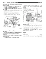
(1) Disconnect the electric and vacuum connectors
from the electric EGR transducer (Fig. 6).
(2) Remove EGR valve mounting bolts.
(3) Clean all gasket surfaces and discard old gas-
kets. Check for any signs of leakage or cracked sur-
faces. Repair or replace as necessary.
INSTALLATION
(1) Install EGR valve and new gasket on intake
manifold. Tighten mounting bolts to 22 N·m (200 in.
lbs.) torque.
(2) Connect the electrical and vacuum connectors
to the electric EGR transducer.
NS
EMISSION CONTROL SYSTEMS
25 - 21
DIAGNOSIS AND TESTING (Continued)
Summary of Contents for 1998 Voyager
Page 8: ...FASTENER IDENTIFICATION NS INTRODUCTION 5 GENERAL INFORMATION Continued ...
Page 9: ...FASTENER STRENGTH 6 INTRODUCTION NS GENERAL INFORMATION Continued ...
Page 11: ...METRIC CONVERSION 8 INTRODUCTION NS GENERAL INFORMATION Continued ...
Page 12: ...TORQUE SPECIFICATIONS NS INTRODUCTION 9 GENERAL INFORMATION Continued ...
Page 16: ......
Page 26: ......
Page 93: ...RED BRAKE WARNING LAMP FUNCTION NS BRAKES 5 11 DIAGNOSIS AND TESTING Continued ...
Page 94: ...POWER BRAKE SYSTEM DIAGNOSTICS 5 12 BRAKES NS DIAGNOSIS AND TESTING Continued ...
Page 95: ...VEHICLE ROAD TEST BRAKE NOISE NS BRAKES 5 13 DIAGNOSIS AND TESTING Continued ...
Page 222: ...COOLING SYSTEM DIAGNOSIS 7 8 COOLING SYSTEM NS DIAGNOSIS AND TESTING Continued ...
Page 223: ...NS COOLING SYSTEM 7 9 DIAGNOSIS AND TESTING Continued ...
Page 224: ...7 10 COOLING SYSTEM NS DIAGNOSIS AND TESTING Continued ...
Page 225: ...NS COOLING SYSTEM 7 11 DIAGNOSIS AND TESTING Continued ...
Page 226: ...7 12 COOLING SYSTEM NS DIAGNOSIS AND TESTING Continued ...
Page 280: ......
Page 286: ......
Page 289: ...CHARGING SYSTEM SCHEMATIC TYPICAL NS CHARGING SYSTEM 8C 3 DIAGNOSIS AND TESTING Continued ...
Page 291: ...CHARGING SYSTEM TEST NS CHARGING SYSTEM 8C 5 DIAGNOSIS AND TESTING Continued ...
Page 292: ...OVERCHARGE TEST 8C 6 CHARGING SYSTEM NS DIAGNOSIS AND TESTING Continued ...
Page 294: ...VOLTAGE DROP TEST 8C 8 CHARGING SYSTEM NS ...
Page 298: ......
Page 372: ......
Page 377: ...NS GS INSTRUMENT PANEL AND SYSTEMS 8E 5 DIAGNOSIS AND TESTING Continued ...
Page 378: ...8E 6 INSTRUMENT PANEL AND SYSTEMS NS GS DIAGNOSIS AND TESTING Continued ...
Page 379: ...NS GS INSTRUMENT PANEL AND SYSTEMS 8E 7 DIAGNOSIS AND TESTING Continued ...
Page 380: ...8E 8 INSTRUMENT PANEL AND SYSTEMS NS GS DIAGNOSIS AND TESTING Continued ...
Page 381: ...NS GS INSTRUMENT PANEL AND SYSTEMS 8E 9 DIAGNOSIS AND TESTING Continued ...
Page 382: ...8E 10 INSTRUMENT PANEL AND SYSTEMS NS GS DIAGNOSIS AND TESTING Continued ...
Page 383: ...NS GS INSTRUMENT PANEL AND SYSTEMS 8E 11 DIAGNOSIS AND TESTING Continued ...
Page 384: ...8E 12 INSTRUMENT PANEL AND SYSTEMS NS GS DIAGNOSIS AND TESTING Continued ...
Page 385: ...NS GS INSTRUMENT PANEL AND SYSTEMS 8E 13 DIAGNOSIS AND TESTING Continued ...
Page 386: ...8E 14 INSTRUMENT PANEL AND SYSTEMS NS GS DIAGNOSIS AND TESTING Continued ...
Page 402: ......
Page 428: ......
Page 440: ......
Page 478: ......
Page 496: ......
Page 504: ......
Page 508: ......
Page 524: ......
Page 542: ......
Page 546: ......
Page 550: ......
Page 559: ...SPECIAL TOOLS SPECIAL TOOL Degausser 6029 NS OVERHEAD CONSOLE 8V 9 ...
Page 560: ......
Page 562: ......
Page 564: ...8W 01 2 8W 01 GENERAL INFORMATION NS GS DESCRIPTION AND OPERATION Continued ...
Page 565: ...NS GS 8W 01 GENERAL INFORMATION 8W 01 3 DESCRIPTION AND OPERATION Continued ...
Page 580: ......
Page 616: ......
Page 660: ......
Page 664: ......
Page 704: ......
Page 718: ......
Page 728: ......
Page 740: ......
Page 744: ......
Page 758: ......
Page 768: ......
Page 784: ......
Page 792: ......
Page 796: ......
Page 800: ......
Page 814: ......
Page 822: ......
Page 826: ......
Page 832: ......
Page 836: ......
Page 840: ......
Page 876: ......
Page 1024: ......
Page 1220: ...Fig 3 Lubrication Lines 9 42 ENGINE NS GS DESCRIPTION AND OPERATION Continued ...
Page 1224: ...ENGINE DIAGNOSIS MECHANICAL CONT 9 46 ENGINE NS GS DIAGNOSIS AND TESTING Continued ...
Page 1286: ...Fig 5 Front Crossmember Dimensions 13 6 FRAME AND BUMPERS NS SPECIFICATIONS Continued ...
Page 1287: ...Fig 6 Engine Compartment Top View NS FRAME AND BUMPERS 13 7 SPECIFICATIONS Continued ...
Page 1289: ...Fig 8 Full Vehicle Bottom View NS FRAME AND BUMPERS 13 9 SPECIFICATIONS Continued ...
Page 1291: ...Fig 11 Body Side Openings NS FRAME AND BUMPERS 13 11 SPECIFICATIONS Continued ...
Page 1292: ......
Page 1302: ...FUEL PRESSURE BELOW SPECIFICATIONS 14 8 FUEL SYSTEM NS DIAGNOSIS AND TESTING Continued ...
Page 1304: ...FUEL INJECTOR DIAGNOSIS 14 10 FUEL SYSTEM NS DIAGNOSIS AND TESTING Continued ...
Page 1368: ......
Page 1426: ......
Page 1472: ......
Page 1479: ...Diagnosis Guide NS TRANSAXLE AND POWER TRANSFER UNIT 21 5 DIAGNOSIS AND TESTING Continued ...
Page 1480: ...Diagnosis Guide 21 6 TRANSAXLE AND POWER TRANSFER UNIT NS DIAGNOSIS AND TESTING Continued ...
Page 1481: ...Diagnosis Guide NS TRANSAXLE AND POWER TRANSFER UNIT 21 7 DIAGNOSIS AND TESTING Continued ...
Page 1482: ...Diagnosis Guide 21 8 TRANSAXLE AND POWER TRANSFER UNIT NS DIAGNOSIS AND TESTING Continued ...
Page 1483: ...Diagnosis Guide NS TRANSAXLE AND POWER TRANSFER UNIT 21 9 DIAGNOSIS AND TESTING Continued ...
Page 1484: ...Diagnosis Guide 21 10 TRANSAXLE AND POWER TRANSFER UNIT NS DIAGNOSIS AND TESTING Continued ...
Page 1485: ...Diagnosis Guide NS TRANSAXLE AND POWER TRANSFER UNIT 21 11 DIAGNOSIS AND TESTING Continued ...
Page 1486: ...Diagnosis Guide 21 12 TRANSAXLE AND POWER TRANSFER UNIT NS DIAGNOSIS AND TESTING Continued ...
Page 1656: ......
Page 1723: ...LEAD CORRECTION CHART NS TIRES AND WHEELS 22 5 DIAGNOSIS AND TESTING Continued ...
Page 1726: ...SPECIFICATIONS TIRE SPECIFICATIONS 22 8 TIRES AND WHEELS NS ...
Page 1866: ......
Page 1904: ......
Page 1928: ......


