BER GLOVES, NOT THE HOUSEHOLD TYPE,
SHOULD BE WORN WHEN REMOVING OR SER-
VICING A BATTERY. SAFETY GLASSES ALSO
SHOULD BE WORN.
DESCRIPTION AND OPERATION
BATTERY IGNITION OFF DRAW (IOD)
A completely normal vehicle will have a small
amount of current drain on the battery with the key
out of the ignition. It can range from 5 to 25 milli-
amperes after all the modules time out. If a vehicle
will not be operated for approximately a 20 days, the
IOD fuse should be pulled to eliminate the vehicle
electrical drain on the battery. The IOD fuse is
located in the Power Distribution Center (PDC).
Refer to the PDC cover for proper fuse.
CHARGING TIME REQUIRED
WARNING:
NEVER
EXCEED
20
AMPS
WHEN
CHARGING A COLD -1°C (30°F) BATTERY. PER-
SONAL INJURY MAY RESULT.
The time required to charge a battery will vary
depending upon the following factors.
SIZE OF BATTERY
A completely discharged large heavy-duty battery
may require more recharging time than a completely
discharged small capacity battery, refer to (Fig. 2) for
charging times.
TEMPERATURE
A longer time will be needed to charge a battery at
-18°C (0°F) than at 27°C (80°F). When a fast charger
is connected to a cold battery, current accepted by
battery will be very low at first. In time, the battery
will accept a higher rate as battery temperature
warms.
CHARGER CAPACITY
A charger which can supply only five amperes will
require a much longer period of charging than a
charger that can supply 20 amperes or more.
STATE OF CHARGE
A completely discharged battery requires more
charging time than a partially charged battery. Elec-
trolyte is nearly pure water in a completely dis-
charged
battery. At
first,
the
charging
current
amperage will be low. As water is converted back to
sulfuric acid inside the battery, the current amp rate
will rise. Also, the specific gravity of the electrolyte
will rise. The electrolyte should be tested with a
Hydrometer to check the specific gravity.
USING HYDROMETER
Before performing a hydrometer test, remove the
battery caps and check the electrolyte level. Add dis-
tilled water as required.
NOTE:
Periodically disassemble the hydrometer
and wash components with soap and water. Inspect
the float for possible leaks. If the paper inside has
turned brown, the float is defective.
Before testing, visually inspect the battery for any
damage:
•
Cracked container or cover
•
Loose post
•
Corrosion
and any other thing that would cause the battery
to be unserviceable. To interpret the hydrometer cor-
rectly, hold it with the top surface of the electrolyte
in the hydrometer at eye level.
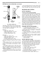
Disregard the curvature of the liquid where the
surface rises against the float because of surface
cohesion (Fig. 3). Remove only enough electrolyte
from the battery to keep the float off the bottom of
the hydrometer barrel with pressure on the bulb
released. Keep the hydrometer in a vertical position
while drawing the electrolyte into the hydrometer
and observing the specific gravity. Exercise care
when inserting the tip of the hydrometer into a cell
to avoid damage to the separators. Damaged separa-
tors can cause premature battery failure.
Hydrometer floats are generally calibrated to indi-
cate the specific gravity correctly only at one fixed
temperature, 20°C (68°F). When testing the specific
gravity at any other temperature, a correction factor
is required, otherwise specific gravity readings will
not indicate the true state of charge.
The correction factor is approximately a specific
gravity value of 0.004, referred to as 4 points of spe-
cific gravity for every 5.5°C (10°F). If electrolyte tem-
perature is below 20°C (68°F) you subtract. If the
temperature is above 20°C (68°F) you add to the
Fig. 2 Battery Charging Time
8A - 2
BATTERY
NS/GS
GENERAL INFORMATION (Continued)
Summary of Contents for 1998 Voyager
Page 8: ...FASTENER IDENTIFICATION NS INTRODUCTION 5 GENERAL INFORMATION Continued ...
Page 9: ...FASTENER STRENGTH 6 INTRODUCTION NS GENERAL INFORMATION Continued ...
Page 11: ...METRIC CONVERSION 8 INTRODUCTION NS GENERAL INFORMATION Continued ...
Page 12: ...TORQUE SPECIFICATIONS NS INTRODUCTION 9 GENERAL INFORMATION Continued ...
Page 16: ......
Page 26: ......
Page 93: ...RED BRAKE WARNING LAMP FUNCTION NS BRAKES 5 11 DIAGNOSIS AND TESTING Continued ...
Page 94: ...POWER BRAKE SYSTEM DIAGNOSTICS 5 12 BRAKES NS DIAGNOSIS AND TESTING Continued ...
Page 95: ...VEHICLE ROAD TEST BRAKE NOISE NS BRAKES 5 13 DIAGNOSIS AND TESTING Continued ...
Page 222: ...COOLING SYSTEM DIAGNOSIS 7 8 COOLING SYSTEM NS DIAGNOSIS AND TESTING Continued ...
Page 223: ...NS COOLING SYSTEM 7 9 DIAGNOSIS AND TESTING Continued ...
Page 224: ...7 10 COOLING SYSTEM NS DIAGNOSIS AND TESTING Continued ...
Page 225: ...NS COOLING SYSTEM 7 11 DIAGNOSIS AND TESTING Continued ...
Page 226: ...7 12 COOLING SYSTEM NS DIAGNOSIS AND TESTING Continued ...
Page 280: ......
Page 286: ......
Page 289: ...CHARGING SYSTEM SCHEMATIC TYPICAL NS CHARGING SYSTEM 8C 3 DIAGNOSIS AND TESTING Continued ...
Page 291: ...CHARGING SYSTEM TEST NS CHARGING SYSTEM 8C 5 DIAGNOSIS AND TESTING Continued ...
Page 292: ...OVERCHARGE TEST 8C 6 CHARGING SYSTEM NS DIAGNOSIS AND TESTING Continued ...
Page 294: ...VOLTAGE DROP TEST 8C 8 CHARGING SYSTEM NS ...
Page 298: ......
Page 372: ......
Page 377: ...NS GS INSTRUMENT PANEL AND SYSTEMS 8E 5 DIAGNOSIS AND TESTING Continued ...
Page 378: ...8E 6 INSTRUMENT PANEL AND SYSTEMS NS GS DIAGNOSIS AND TESTING Continued ...
Page 379: ...NS GS INSTRUMENT PANEL AND SYSTEMS 8E 7 DIAGNOSIS AND TESTING Continued ...
Page 380: ...8E 8 INSTRUMENT PANEL AND SYSTEMS NS GS DIAGNOSIS AND TESTING Continued ...
Page 381: ...NS GS INSTRUMENT PANEL AND SYSTEMS 8E 9 DIAGNOSIS AND TESTING Continued ...
Page 382: ...8E 10 INSTRUMENT PANEL AND SYSTEMS NS GS DIAGNOSIS AND TESTING Continued ...
Page 383: ...NS GS INSTRUMENT PANEL AND SYSTEMS 8E 11 DIAGNOSIS AND TESTING Continued ...
Page 384: ...8E 12 INSTRUMENT PANEL AND SYSTEMS NS GS DIAGNOSIS AND TESTING Continued ...
Page 385: ...NS GS INSTRUMENT PANEL AND SYSTEMS 8E 13 DIAGNOSIS AND TESTING Continued ...
Page 386: ...8E 14 INSTRUMENT PANEL AND SYSTEMS NS GS DIAGNOSIS AND TESTING Continued ...
Page 402: ......
Page 428: ......
Page 440: ......
Page 478: ......
Page 496: ......
Page 504: ......
Page 508: ......
Page 524: ......
Page 542: ......
Page 546: ......
Page 550: ......
Page 559: ...SPECIAL TOOLS SPECIAL TOOL Degausser 6029 NS OVERHEAD CONSOLE 8V 9 ...
Page 560: ......
Page 562: ......
Page 564: ...8W 01 2 8W 01 GENERAL INFORMATION NS GS DESCRIPTION AND OPERATION Continued ...
Page 565: ...NS GS 8W 01 GENERAL INFORMATION 8W 01 3 DESCRIPTION AND OPERATION Continued ...
Page 580: ......
Page 616: ......
Page 660: ......
Page 664: ......
Page 704: ......
Page 718: ......
Page 728: ......
Page 740: ......
Page 744: ......
Page 758: ......
Page 768: ......
Page 784: ......
Page 792: ......
Page 796: ......
Page 800: ......
Page 814: ......
Page 822: ......
Page 826: ......
Page 832: ......
Page 836: ......
Page 840: ......
Page 876: ......
Page 1024: ......
Page 1220: ...Fig 3 Lubrication Lines 9 42 ENGINE NS GS DESCRIPTION AND OPERATION Continued ...
Page 1224: ...ENGINE DIAGNOSIS MECHANICAL CONT 9 46 ENGINE NS GS DIAGNOSIS AND TESTING Continued ...
Page 1286: ...Fig 5 Front Crossmember Dimensions 13 6 FRAME AND BUMPERS NS SPECIFICATIONS Continued ...
Page 1287: ...Fig 6 Engine Compartment Top View NS FRAME AND BUMPERS 13 7 SPECIFICATIONS Continued ...
Page 1289: ...Fig 8 Full Vehicle Bottom View NS FRAME AND BUMPERS 13 9 SPECIFICATIONS Continued ...
Page 1291: ...Fig 11 Body Side Openings NS FRAME AND BUMPERS 13 11 SPECIFICATIONS Continued ...
Page 1292: ......
Page 1302: ...FUEL PRESSURE BELOW SPECIFICATIONS 14 8 FUEL SYSTEM NS DIAGNOSIS AND TESTING Continued ...
Page 1304: ...FUEL INJECTOR DIAGNOSIS 14 10 FUEL SYSTEM NS DIAGNOSIS AND TESTING Continued ...
Page 1368: ......
Page 1426: ......
Page 1472: ......
Page 1479: ...Diagnosis Guide NS TRANSAXLE AND POWER TRANSFER UNIT 21 5 DIAGNOSIS AND TESTING Continued ...
Page 1480: ...Diagnosis Guide 21 6 TRANSAXLE AND POWER TRANSFER UNIT NS DIAGNOSIS AND TESTING Continued ...
Page 1481: ...Diagnosis Guide NS TRANSAXLE AND POWER TRANSFER UNIT 21 7 DIAGNOSIS AND TESTING Continued ...
Page 1482: ...Diagnosis Guide 21 8 TRANSAXLE AND POWER TRANSFER UNIT NS DIAGNOSIS AND TESTING Continued ...
Page 1483: ...Diagnosis Guide NS TRANSAXLE AND POWER TRANSFER UNIT 21 9 DIAGNOSIS AND TESTING Continued ...
Page 1484: ...Diagnosis Guide 21 10 TRANSAXLE AND POWER TRANSFER UNIT NS DIAGNOSIS AND TESTING Continued ...
Page 1485: ...Diagnosis Guide NS TRANSAXLE AND POWER TRANSFER UNIT 21 11 DIAGNOSIS AND TESTING Continued ...
Page 1486: ...Diagnosis Guide 21 12 TRANSAXLE AND POWER TRANSFER UNIT NS DIAGNOSIS AND TESTING Continued ...
Page 1656: ......
Page 1723: ...LEAD CORRECTION CHART NS TIRES AND WHEELS 22 5 DIAGNOSIS AND TESTING Continued ...
Page 1726: ...SPECIFICATIONS TIRE SPECIFICATIONS 22 8 TIRES AND WHEELS NS ...
Page 1866: ......
Page 1904: ......
Page 1928: ......


