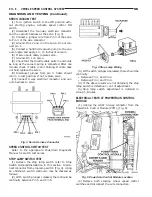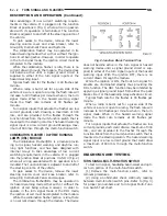
take advantage of low current switching require-
ments in the vehicle. It is plugged into the Junction
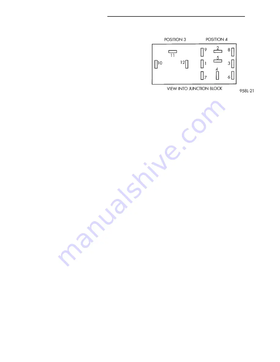
Block at positions 4 (Fig. 1) where all wiring associ-
ated with its operation is terminated. The Junction
Block is adjacent to and left of the steering column of
the vehicle.
To gain access to the device, remove the lower
steering column cover and knee blocker, refer to
Group 8E, Instrument Panel and Systems.
The combination flasher may be operated in its
hazard warning mode either with or without the igni-
tion circuit being active. However, in order to operate
in the turn signal mode, the ignition circuit must be
completed to the module.
While the combination flasher is idle, there is no
current drawn through the module. The device does
not become active until a signal ground circuit is
supplied to either of the turn signal inputs or the
hazard warning input.
Typical flash rate for the flasher is 90 flashes per
minute.
When a lamp is burnt out for a given side of the
vehicle or a wire is open to a lamp, the flash rate will
increase to 180 flashes per minute when in the turn
signal mode. When in the hazard warning signal
mode the flash rate remains at 90 flashes per
minute.
Turn signal inputs that actuate the flasher are low
current grounds, each drawing a maximum of 300
mA., and are provided to the flasher through the
Junction Block from the multi-function switch that is
mounted to the steering column. The hazard warning
signal input is a low current ground drawing a max-
imum of 600 mA. through the multi-function switch.
COMBINATION FLASHER / DAYTIME RUNNING
LAMPS (DRL) MODULE
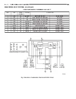
The Combination Flasher/DRL is a module provid-
ing turn signal, hazard warning, and daytime run-
ning light functions, and has been designed with
internal relays to take advantage of low current
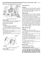
switching requirements in the vehicle. It is plugged
into the junction block at positions 3 AND 4 (Fig. 2)
where all wiring associated with its operation is ter-
minated. The Junction Block is adjacent to and left of
the steering column of the vehicle.
To gain access to the device, remove the lower
steering column cover and knee blocker, refer to
Group 8E, Instrument Panel and Gauges.
The combination flasher/DRL may be operated in
its hazard warning mode either with or without the
ignition circuit being active. However, in order to
operate in the turn signal mode or the DRL mode,
the ignition circuit must be completed to the module.
While the combination flasher portion is idle, there
is no current drawn through the module. The device
does not become active in the turn signal or hazard
warning modes until a signal ground circuit is sup-
plied to either of the turn signal inputs or the hazard
warning input. With the ignition OFF, there is no
current drawn through the module.
While the ignition is ON, the front turn signal fil-
aments are illuminated steadily thus providing the
DRL function. The DRL function may be inhibited by
applying a signal ground input from either the park
brake circuit or the headlamp relay activation circuit.
Typical flash rate for the flasher is 90 flashes per
minute.
When a lamp is burnt out for a given side of the
vehicle or a wire is open to a lamp, the flash rate will
increase to 180 flashes per minute when in the turn
signal mode. When in the hazard warning signal
mode the flash rate remains at 90 flashes per
minute.
Turn signal inputs that actuate the flasher are low
current grounds, each could draw a maximum of 300
mA., and are provided to the flasher through the
Junction Block from the multi-function switch that is
mounted to the steering column. The hazard warning
signal input is a low current ground that could draw
a maximum of 600 mA. through the multi-function
switch.
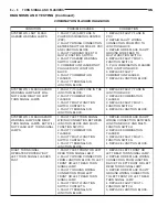
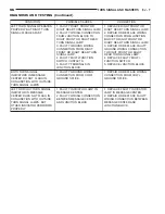
DIAGNOSIS AND TESTING
TURN SIGNAL MULTI-FUNCTION SWITCH
To test turn signal, headlamp beam select and opti-
cal horn portion of the multi-function switch:
(1) Remove the multi-function switch, refer to
removal procedures.
(2) Using an ohmmeter check continuity reading
between multi-function switch pins. Refer to (Fig. 3)
for proper pin numbers and Turn Signal Multi-Func-
tion Switch Test chart.
Fig. 2 Junction Block Terminal Pins
8J - 2
TURN SIGNAL AND FLASHERS
NS
DESCRIPTION AND OPERATION (Continued)
Summary of Contents for 1998 Voyager
Page 8: ...FASTENER IDENTIFICATION NS INTRODUCTION 5 GENERAL INFORMATION Continued ...
Page 9: ...FASTENER STRENGTH 6 INTRODUCTION NS GENERAL INFORMATION Continued ...
Page 11: ...METRIC CONVERSION 8 INTRODUCTION NS GENERAL INFORMATION Continued ...
Page 12: ...TORQUE SPECIFICATIONS NS INTRODUCTION 9 GENERAL INFORMATION Continued ...
Page 16: ......
Page 26: ......
Page 93: ...RED BRAKE WARNING LAMP FUNCTION NS BRAKES 5 11 DIAGNOSIS AND TESTING Continued ...
Page 94: ...POWER BRAKE SYSTEM DIAGNOSTICS 5 12 BRAKES NS DIAGNOSIS AND TESTING Continued ...
Page 95: ...VEHICLE ROAD TEST BRAKE NOISE NS BRAKES 5 13 DIAGNOSIS AND TESTING Continued ...
Page 222: ...COOLING SYSTEM DIAGNOSIS 7 8 COOLING SYSTEM NS DIAGNOSIS AND TESTING Continued ...
Page 223: ...NS COOLING SYSTEM 7 9 DIAGNOSIS AND TESTING Continued ...
Page 224: ...7 10 COOLING SYSTEM NS DIAGNOSIS AND TESTING Continued ...
Page 225: ...NS COOLING SYSTEM 7 11 DIAGNOSIS AND TESTING Continued ...
Page 226: ...7 12 COOLING SYSTEM NS DIAGNOSIS AND TESTING Continued ...
Page 280: ......
Page 286: ......
Page 289: ...CHARGING SYSTEM SCHEMATIC TYPICAL NS CHARGING SYSTEM 8C 3 DIAGNOSIS AND TESTING Continued ...
Page 291: ...CHARGING SYSTEM TEST NS CHARGING SYSTEM 8C 5 DIAGNOSIS AND TESTING Continued ...
Page 292: ...OVERCHARGE TEST 8C 6 CHARGING SYSTEM NS DIAGNOSIS AND TESTING Continued ...
Page 294: ...VOLTAGE DROP TEST 8C 8 CHARGING SYSTEM NS ...
Page 298: ......
Page 372: ......
Page 377: ...NS GS INSTRUMENT PANEL AND SYSTEMS 8E 5 DIAGNOSIS AND TESTING Continued ...
Page 378: ...8E 6 INSTRUMENT PANEL AND SYSTEMS NS GS DIAGNOSIS AND TESTING Continued ...
Page 379: ...NS GS INSTRUMENT PANEL AND SYSTEMS 8E 7 DIAGNOSIS AND TESTING Continued ...
Page 380: ...8E 8 INSTRUMENT PANEL AND SYSTEMS NS GS DIAGNOSIS AND TESTING Continued ...
Page 381: ...NS GS INSTRUMENT PANEL AND SYSTEMS 8E 9 DIAGNOSIS AND TESTING Continued ...
Page 382: ...8E 10 INSTRUMENT PANEL AND SYSTEMS NS GS DIAGNOSIS AND TESTING Continued ...
Page 383: ...NS GS INSTRUMENT PANEL AND SYSTEMS 8E 11 DIAGNOSIS AND TESTING Continued ...
Page 384: ...8E 12 INSTRUMENT PANEL AND SYSTEMS NS GS DIAGNOSIS AND TESTING Continued ...
Page 385: ...NS GS INSTRUMENT PANEL AND SYSTEMS 8E 13 DIAGNOSIS AND TESTING Continued ...
Page 386: ...8E 14 INSTRUMENT PANEL AND SYSTEMS NS GS DIAGNOSIS AND TESTING Continued ...
Page 402: ......
Page 428: ......
Page 440: ......
Page 478: ......
Page 496: ......
Page 504: ......
Page 508: ......
Page 524: ......
Page 542: ......
Page 546: ......
Page 550: ......
Page 559: ...SPECIAL TOOLS SPECIAL TOOL Degausser 6029 NS OVERHEAD CONSOLE 8V 9 ...
Page 560: ......
Page 562: ......
Page 564: ...8W 01 2 8W 01 GENERAL INFORMATION NS GS DESCRIPTION AND OPERATION Continued ...
Page 565: ...NS GS 8W 01 GENERAL INFORMATION 8W 01 3 DESCRIPTION AND OPERATION Continued ...
Page 580: ......
Page 616: ......
Page 660: ......
Page 664: ......
Page 704: ......
Page 718: ......
Page 728: ......
Page 740: ......
Page 744: ......
Page 758: ......
Page 768: ......
Page 784: ......
Page 792: ......
Page 796: ......
Page 800: ......
Page 814: ......
Page 822: ......
Page 826: ......
Page 832: ......
Page 836: ......
Page 840: ......
Page 876: ......
Page 1024: ......
Page 1220: ...Fig 3 Lubrication Lines 9 42 ENGINE NS GS DESCRIPTION AND OPERATION Continued ...
Page 1224: ...ENGINE DIAGNOSIS MECHANICAL CONT 9 46 ENGINE NS GS DIAGNOSIS AND TESTING Continued ...
Page 1286: ...Fig 5 Front Crossmember Dimensions 13 6 FRAME AND BUMPERS NS SPECIFICATIONS Continued ...
Page 1287: ...Fig 6 Engine Compartment Top View NS FRAME AND BUMPERS 13 7 SPECIFICATIONS Continued ...
Page 1289: ...Fig 8 Full Vehicle Bottom View NS FRAME AND BUMPERS 13 9 SPECIFICATIONS Continued ...
Page 1291: ...Fig 11 Body Side Openings NS FRAME AND BUMPERS 13 11 SPECIFICATIONS Continued ...
Page 1292: ......
Page 1302: ...FUEL PRESSURE BELOW SPECIFICATIONS 14 8 FUEL SYSTEM NS DIAGNOSIS AND TESTING Continued ...
Page 1304: ...FUEL INJECTOR DIAGNOSIS 14 10 FUEL SYSTEM NS DIAGNOSIS AND TESTING Continued ...
Page 1368: ......
Page 1426: ......
Page 1472: ......
Page 1479: ...Diagnosis Guide NS TRANSAXLE AND POWER TRANSFER UNIT 21 5 DIAGNOSIS AND TESTING Continued ...
Page 1480: ...Diagnosis Guide 21 6 TRANSAXLE AND POWER TRANSFER UNIT NS DIAGNOSIS AND TESTING Continued ...
Page 1481: ...Diagnosis Guide NS TRANSAXLE AND POWER TRANSFER UNIT 21 7 DIAGNOSIS AND TESTING Continued ...
Page 1482: ...Diagnosis Guide 21 8 TRANSAXLE AND POWER TRANSFER UNIT NS DIAGNOSIS AND TESTING Continued ...
Page 1483: ...Diagnosis Guide NS TRANSAXLE AND POWER TRANSFER UNIT 21 9 DIAGNOSIS AND TESTING Continued ...
Page 1484: ...Diagnosis Guide 21 10 TRANSAXLE AND POWER TRANSFER UNIT NS DIAGNOSIS AND TESTING Continued ...
Page 1485: ...Diagnosis Guide NS TRANSAXLE AND POWER TRANSFER UNIT 21 11 DIAGNOSIS AND TESTING Continued ...
Page 1486: ...Diagnosis Guide 21 12 TRANSAXLE AND POWER TRANSFER UNIT NS DIAGNOSIS AND TESTING Continued ...
Page 1656: ......
Page 1723: ...LEAD CORRECTION CHART NS TIRES AND WHEELS 22 5 DIAGNOSIS AND TESTING Continued ...
Page 1726: ...SPECIFICATIONS TIRE SPECIFICATIONS 22 8 TIRES AND WHEELS NS ...
Page 1866: ......
Page 1904: ......
Page 1928: ......

