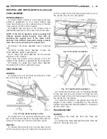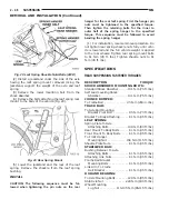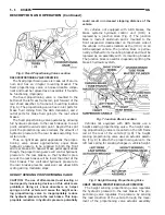
(Fig. 8). The actuator assembly is mounted between
the height sensing proportioning valve and the actua-
tor bracket on the left rear leaf spring (Fig. 8). As the
rear height of the vehicle changes depending on the
load the vehicle is carrying the height change is
transferred to the height sensing proportioning valve.
This change in vehicle height is transferred through
the movement of the left rear leaf spring. As the posi-
tion of the left rear leaf spring changes this move-
ment is transferred through the actuator bracket
(Fig. 8) to the actuator assembly (Fig. 8) and then to
the proportioning valve.
Thus,
the
height
sensing
proportioning
valve
allows the brake system to maintain the optimal
front to rear brake balance regardless of the vehicle
load condition. Under a light load condition, hydrau-
lic pressure to the rear brakes is minimized. As the
load condition of the vehicle increases, so does the
hydraulic pressure to the rear brakes.
The proportioning valve section of the valve oper-
ates by transmitting full input hydraulic pressure to
the rear brakes up to a certain point, called the split
point. Beyond the split point the proportioning valve
reduces the amount of hydraulic pressure to the rear
brakes according to a certain ratio. Thus, on light
brake applications, approximately equal hydraulic
pressure will be transmitted to the front and rear
brakes. At heavier brake applications, the hydraulic
pressure transmitted to the rear brakes will be lower
then the front brakes. This will prevent premature
rear wheel lock-up and skid.
The height sensing section of the valve thus
changes the split point of the proportioning valve,
based on the rear suspension height of the vehicle.
When the height of the rear suspension is low, the
proportioning valve interprets this as extra load and
the split point of the proportioning valve is raised to
allow more rear braking. When the height of the rear
suspension is high, the proportioning valve interprets
this as a lightly loaded vehicle and the split point of
the proportioning valve is lowered and rear braking
is reduced.
CHASSIS TUBES AND HOSES
The purpose of the chassis brake tubes and flex
hoses is to transfer the pressurized brake fluid devel-
oped by the master cylinder to the wheel brakes of
the vehicle. The chassis tubes are steel with a corro-
sion resistant coating applied to the external surfaces
and the flex hoses are made of reinforced rubber. The
rubber flex hoses allow for the movement of the vehi-
cles suspension.
MASTER CYLINDER
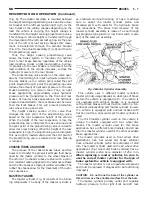
The master cylinder (Fig. 9) consists of the follow-
ing components. The body of the master cylinder is
an anodized aluminum casting. It has a machined
bore to accept the master cylinder piston and
threaded ports with seats for the hydraulic brake
line connections. The brake fluid reservoir of the
master cylinder assembly is made of a see through
polypropylene type plastic. A low fluid switch is also
part of the reservoir assembly.
This vehicle uses 3 different master cylinders.
Master cylinder usage depends on what type of brake
system the vehicle is equipped with. If a vehicle is
not equipped with antilock brakes, or is equipped
with antilock brakes without traction control, a con-
ventional compensating port master cylinder is used.
If a vehicle is equipped with antilock brakes with
traction control, a dual center port master cylinder is
used.
The third master cylinder used on this vehicle is
unique to vehicles equipped with four wheel disc
brakes. The master cylinder used for this brake
application has a different bore diameter and stroke
then the master cylinder used for the other available
brake applications.
The master cylinders used on front wheel drive
applications (non four wheel disc brake vehicles)
have a master cylinder piston bore diameter of 23.8
mm. The master cylinder used on the all wheel drive
applications (four wheel disc brake vehicles) have a
master cylinder piston bore diameter of 25.4 mm.
When replacing a master cylinder, be sure to
use the correct master cylinder for the type of
brake system the vehicle is equipped with.
The master cylinder is not a repairable component
and must be replaced if diagnosed to be functioning
improperly
CAUTION:
Do not hone the bore of the cylinder as
this will remove the anodized surface from the bore.
The master cylinder primary outlet port supplies
hydraulic pressure to the right front and left rear
Fig. 9 Master Cylinder Assembly
NS
BRAKES
5 - 7
DESCRIPTION AND OPERATION (Continued)
Summary of Contents for 1998 Voyager
Page 8: ...FASTENER IDENTIFICATION NS INTRODUCTION 5 GENERAL INFORMATION Continued ...
Page 9: ...FASTENER STRENGTH 6 INTRODUCTION NS GENERAL INFORMATION Continued ...
Page 11: ...METRIC CONVERSION 8 INTRODUCTION NS GENERAL INFORMATION Continued ...
Page 12: ...TORQUE SPECIFICATIONS NS INTRODUCTION 9 GENERAL INFORMATION Continued ...
Page 16: ......
Page 26: ......
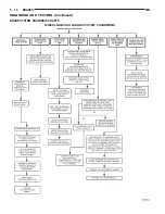
Page 93: ...RED BRAKE WARNING LAMP FUNCTION NS BRAKES 5 11 DIAGNOSIS AND TESTING Continued ...
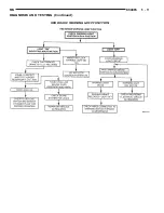
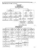
Page 94: ...POWER BRAKE SYSTEM DIAGNOSTICS 5 12 BRAKES NS DIAGNOSIS AND TESTING Continued ...
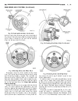
Page 95: ...VEHICLE ROAD TEST BRAKE NOISE NS BRAKES 5 13 DIAGNOSIS AND TESTING Continued ...
Page 222: ...COOLING SYSTEM DIAGNOSIS 7 8 COOLING SYSTEM NS DIAGNOSIS AND TESTING Continued ...
Page 223: ...NS COOLING SYSTEM 7 9 DIAGNOSIS AND TESTING Continued ...
Page 224: ...7 10 COOLING SYSTEM NS DIAGNOSIS AND TESTING Continued ...
Page 225: ...NS COOLING SYSTEM 7 11 DIAGNOSIS AND TESTING Continued ...
Page 226: ...7 12 COOLING SYSTEM NS DIAGNOSIS AND TESTING Continued ...
Page 280: ......
Page 286: ......
Page 289: ...CHARGING SYSTEM SCHEMATIC TYPICAL NS CHARGING SYSTEM 8C 3 DIAGNOSIS AND TESTING Continued ...
Page 291: ...CHARGING SYSTEM TEST NS CHARGING SYSTEM 8C 5 DIAGNOSIS AND TESTING Continued ...
Page 292: ...OVERCHARGE TEST 8C 6 CHARGING SYSTEM NS DIAGNOSIS AND TESTING Continued ...
Page 294: ...VOLTAGE DROP TEST 8C 8 CHARGING SYSTEM NS ...
Page 298: ......
Page 372: ......
Page 377: ...NS GS INSTRUMENT PANEL AND SYSTEMS 8E 5 DIAGNOSIS AND TESTING Continued ...
Page 378: ...8E 6 INSTRUMENT PANEL AND SYSTEMS NS GS DIAGNOSIS AND TESTING Continued ...
Page 379: ...NS GS INSTRUMENT PANEL AND SYSTEMS 8E 7 DIAGNOSIS AND TESTING Continued ...
Page 380: ...8E 8 INSTRUMENT PANEL AND SYSTEMS NS GS DIAGNOSIS AND TESTING Continued ...
Page 381: ...NS GS INSTRUMENT PANEL AND SYSTEMS 8E 9 DIAGNOSIS AND TESTING Continued ...
Page 382: ...8E 10 INSTRUMENT PANEL AND SYSTEMS NS GS DIAGNOSIS AND TESTING Continued ...
Page 383: ...NS GS INSTRUMENT PANEL AND SYSTEMS 8E 11 DIAGNOSIS AND TESTING Continued ...
Page 384: ...8E 12 INSTRUMENT PANEL AND SYSTEMS NS GS DIAGNOSIS AND TESTING Continued ...
Page 385: ...NS GS INSTRUMENT PANEL AND SYSTEMS 8E 13 DIAGNOSIS AND TESTING Continued ...
Page 386: ...8E 14 INSTRUMENT PANEL AND SYSTEMS NS GS DIAGNOSIS AND TESTING Continued ...
Page 402: ......
Page 428: ......
Page 440: ......
Page 478: ......
Page 496: ......
Page 504: ......
Page 508: ......
Page 524: ......
Page 542: ......
Page 546: ......
Page 550: ......
Page 559: ...SPECIAL TOOLS SPECIAL TOOL Degausser 6029 NS OVERHEAD CONSOLE 8V 9 ...
Page 560: ......
Page 562: ......
Page 564: ...8W 01 2 8W 01 GENERAL INFORMATION NS GS DESCRIPTION AND OPERATION Continued ...
Page 565: ...NS GS 8W 01 GENERAL INFORMATION 8W 01 3 DESCRIPTION AND OPERATION Continued ...
Page 580: ......
Page 616: ......
Page 660: ......
Page 664: ......
Page 704: ......
Page 718: ......
Page 728: ......
Page 740: ......
Page 744: ......
Page 758: ......
Page 768: ......
Page 784: ......
Page 792: ......
Page 796: ......
Page 800: ......
Page 814: ......
Page 822: ......
Page 826: ......
Page 832: ......
Page 836: ......
Page 840: ......
Page 876: ......
Page 1024: ......
Page 1220: ...Fig 3 Lubrication Lines 9 42 ENGINE NS GS DESCRIPTION AND OPERATION Continued ...
Page 1224: ...ENGINE DIAGNOSIS MECHANICAL CONT 9 46 ENGINE NS GS DIAGNOSIS AND TESTING Continued ...
Page 1286: ...Fig 5 Front Crossmember Dimensions 13 6 FRAME AND BUMPERS NS SPECIFICATIONS Continued ...
Page 1287: ...Fig 6 Engine Compartment Top View NS FRAME AND BUMPERS 13 7 SPECIFICATIONS Continued ...
Page 1289: ...Fig 8 Full Vehicle Bottom View NS FRAME AND BUMPERS 13 9 SPECIFICATIONS Continued ...
Page 1291: ...Fig 11 Body Side Openings NS FRAME AND BUMPERS 13 11 SPECIFICATIONS Continued ...
Page 1292: ......
Page 1302: ...FUEL PRESSURE BELOW SPECIFICATIONS 14 8 FUEL SYSTEM NS DIAGNOSIS AND TESTING Continued ...
Page 1304: ...FUEL INJECTOR DIAGNOSIS 14 10 FUEL SYSTEM NS DIAGNOSIS AND TESTING Continued ...
Page 1368: ......
Page 1426: ......
Page 1472: ......
Page 1479: ...Diagnosis Guide NS TRANSAXLE AND POWER TRANSFER UNIT 21 5 DIAGNOSIS AND TESTING Continued ...
Page 1480: ...Diagnosis Guide 21 6 TRANSAXLE AND POWER TRANSFER UNIT NS DIAGNOSIS AND TESTING Continued ...
Page 1481: ...Diagnosis Guide NS TRANSAXLE AND POWER TRANSFER UNIT 21 7 DIAGNOSIS AND TESTING Continued ...
Page 1482: ...Diagnosis Guide 21 8 TRANSAXLE AND POWER TRANSFER UNIT NS DIAGNOSIS AND TESTING Continued ...
Page 1483: ...Diagnosis Guide NS TRANSAXLE AND POWER TRANSFER UNIT 21 9 DIAGNOSIS AND TESTING Continued ...
Page 1484: ...Diagnosis Guide 21 10 TRANSAXLE AND POWER TRANSFER UNIT NS DIAGNOSIS AND TESTING Continued ...
Page 1485: ...Diagnosis Guide NS TRANSAXLE AND POWER TRANSFER UNIT 21 11 DIAGNOSIS AND TESTING Continued ...
Page 1486: ...Diagnosis Guide 21 12 TRANSAXLE AND POWER TRANSFER UNIT NS DIAGNOSIS AND TESTING Continued ...
Page 1656: ......
Page 1723: ...LEAD CORRECTION CHART NS TIRES AND WHEELS 22 5 DIAGNOSIS AND TESTING Continued ...
Page 1726: ...SPECIFICATIONS TIRE SPECIFICATIONS 22 8 TIRES AND WHEELS NS ...
Page 1866: ......
Page 1904: ......
Page 1928: ......


