background image

Summary of Contents for Imperial 1962

Page 1: ...10 1 S E R V I C E 10VL M A N U A L ...

Page 2: ... LeBaron SY 1 HY 1 The service tools referred to in this Manual are avail able through the Miller Manufacturing Company 17640 Grand River Avenue Detroit 27 Michigan U S A unless otherwise specified Extra copies of this Manual are available at 5 00 each plus any local taxes under Part Number 81 070 2072 Order from Chrysler Plymouth Division P O Box 1658 Detroit 31 Michigan CHRYSLER PLYMOUTH DIVISIO...

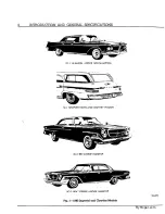
Page 3: ...ION AND GENERAL SPECIFICATIONS SY 1 LE BARON 4 DCOR SOUTHAMPTON SC l NEWPORT TOWN AND COUNTRY WAGON SC 2 300 2 DOOR HARDTOP SC 3 NEW YORKER 4 DOOR HARDTOP 62x372 Fig 1 1962 Imperial and Chrfsler Models MyMopar com ...

Page 4: ...dations as to what should be done and the reason for so doing Include Paint and Trim Code Numbers where finish upholstery body or sheet metal is in volved and estimate of net cost of repairs CHRYSLER PLYMOUTH DIVISION With the exception of orders for parts or parts literature all requests for Chrysler and Imperial Service literature such as Service Bulletins Service Manuals Owner Manuals Time Sche...

Page 5: ...ion P O Box 10786 Funston Chrysler Roads Atlanta 10 Georgia Kansas City 15 Kansas Telephone Atlanta Telephone Kansas City Kansas Plaza 5 2531 Fairfax 1 3300 Parts Division Literature Request for Parts Division literature such as Parts Books Parts Price Lists Parts Bulletins etc should be forwarded direct to Chrysler Corporation Parts Division P O Box 1718 Detroit 31 Michigan Attention Parts Catalo...

Page 6: ...SC 3 83 23100001 New Yorker Town and Country SC 3 87 23100001 Chrysler 300H SC 2 300H 84 23100001 IMPERIAL MODELS Custom SY 1 91 23100001 Crown SY 1 92 23100001 LeBaron SY 1 93 23100001 Model 1 Serial Number The starting engine numbers will be as follows CHRYSLER Newport S 36 8 7 300 S 38 8 7 New Yorker S 41 8 7 Chrysler 300H S 41 8 7 IMPERIAL S 41 8 7 Fig 2 Vehicle Number The vehicle number is st...

Page 7: ...ead Four Door Sedan 59 7 59 7 Rear Convertible Coupe 59 7 59 7f 62 2 Two Door hard top 59 7 59 7f 62 2 Town Country 59 7 60 0 Four Door hard top 59 7 59 7f 59 7 62 2 Length with Four Door Sedan 214 9 219 3 Bumper Convertible Coupe 214 9 214 9 227 1 Two Door hard top 214 9 214 9 227 1 Town Country 216 4 220 4 Four Door hard top 214 9 214 9 209 3 227 1 Width with Four Door Sedan 79 4 79 4 Bumper Con...

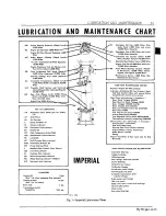
Page 8: ...00 Miles Wick under Rotor 3 000 Miles and every 12 000 Miles thereafter Distributor Cam 8 000 Miles and every 12 000 Miles thereafter Carburetor Air Cleaner Clean 8 000 Miles Replace Element 32 000 Miles S Manifold Heat Control Valve 4 000 Miles Engine Tune Up at 8 000 Miles and every 12 000 Miles thereafter WB Front Wheel Bearings Inspect Repack if Necesscry 16 000 Miles Clean Repack and Adjust 3...

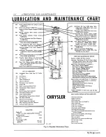
Page 9: ...ck under Rotor 8 000 Miles and every 12 000 Miles thereafter DCL Distributor Cam 8 000 Miles and every 12 000 Miles thereafter Carburetor A i r Cleaner Clean 8 000 Miles Replace Element 32 000 Miles S Manifold Heat Control Valve 4 000 Miles Engine Tune Up at 8 000 Miles and every 12 000 Miles thereafter WB Front Wheel Bearings Inspect Repack if Necessary 16 000 Miles Clean Repack and Adjust 32 000...

Page 10: ...00 Miles Wick under Rotor 3 000 Miles and every 12 000 Miles thereafter Distributor Cam 8 000 Miles and every 12 000 Miles thereafter Carburetor Air Cleaner Clean 8 000 Miles Replace Element 32 000 Miles S Manifold Heat Control Valve 4 000 Miles Engine Tune Up at 8 000 Miles and every 12 000 Miles thereafter WB Front Wheel Bearings Inspect Repack if Necesscry 16 000 Miles Clean Repack and Adjust 3...

Page 11: ...ck under Rotor 8 000 Miles and every 12 000 Miles thereafter DCL Distributor Cam 8 000 Miles and every 12 000 Miles thereafter Carburetor A i r Cleaner Clean 8 000 Miles Replace Element 32 000 Miles S Manifold Heat Control Valve 4 000 Miles Engine Tune Up at 8 000 Miles and every 12 000 Miles thereafter WB Front Wheel Bearings Inspect Repack if Necessary 16 000 Miles Clean Repack and Adjust 32 000...

Page 12: ...Cooling System 8 Crankcase Ventilation Outlet Pipe Air Cleaner 12 Crankcase Ventilator Valve 12 Data and Specifications 4 Distributor 9 Engine Oil 5 Engine Oil Filter 9 Front Wheel Bearings 12 Fuel Filter 13 Manifold Heat Control Valve 9 Parts Requiring No Lubrication 13 Rear Axle 9 Rear Axle with Sure Grip D i f f e r e n t i a l 10 Speedometer Cable 10 Steering 10 Tires 10 Transmission 11 Univer...

Page 13: ... 14x5 8 SC l Newport Town and Country 16 5 21 4M 19 4 8 50x14 4 22 24 14x6K 8 SC 2 300 16 5 23 4K 19 4 8 00xl4 4 24 22 14x5H Chrysler 8 SC 3 New Yorker 16 5 23 NA 19 4 8 50x14 4 24 22 14x6K 8 SC 3 New Yorker Town and Country 16 5 21 NA 19 4 9 00x14 4 22 24 14x6J K 8 SY 1 Custom 16 5 23 NA 19 4 8 20x15 4 24 24 15x6L Imperial 8 SY 1 Crown 16 5 23 NA 19 4 8 20x15 4 24 24 15x6L 8 SY 1 LeBaron 16 5 23 ...

Page 14: ...e made as frequently as every 500 miles Crosscountry driving with good oils will permit 4 000 miles of operation between changes Chrysler Corporation has determined that the type of operation by the average driver indicates that the engine oil should be changed approximately every two months for traffic driving or every 4 000 miles for highway driving The oil added to the engine at the factory is ...

Page 15: ...ittle as a pin point puncture Examine the soft plastic sealer on both sides of the element These sealing surfaces must be smooth and uniform BODY The following parts should be inspected at every 4 000 mile oil change and lubricated if necessary Prior to applying any lubricants parts should be wiped clean to remove dust and grit After lubrica tion excess oil or grease should be removed Particu lar ...

Page 16: ...to the pivot points directly every 4 000 miles Lubricate parking brake linkage external con tracting manual transmission only with engine oil CHASSIS LUBRICATION a Front Suspension Ball Joints All ball joints and the torsion bars are effectively sealed against road splash by tightly fitted balloon type flexible seals The ball joints are semi perma nently lubricated with a special lubricant Part Nu...

Page 17: ...vot or center link pivot joint seals are cut or damaged install new seals to pre vent further lubricant leakage and subsequent joint failure Whenever an engine oil pan is removed and if it is necessary to remove the steering linkage recommended tools should be used to prevent joint and seal damage COOLING SYSTEM The cooling system should be drained rinsed and re filled with the proper coolant in t...

Page 18: ...lubricant has been wiped off ENGINE OIL FILTER Efficient filtering of the oil is very important to pro vide good engine protection Fig 11 The oil filter should be replaced every 4 000 miles and should coincide with an engine oil change Short trip stop and go operation or operation in dusty areas may require more frequent filter changes MANIFOLD HEAT CONTROL VALVE Every 4 000 miles apply Manifold H...

Page 19: ...the filler hole Refill to the bot tom of the filler hole using the correct lubricant type and viscosity grade according to the anticipated temperature range Install the plug Hypoid Lubricant Part Number 1879414 Anticipated Temperature Viscosity Range Grade Above 10 F SAE 90 As Low as 30 F SAE 80 Below 30 F SAE 75 STEERING a Manual Steering Every 4 000 miles check the lubricant level Replen ish wit...

Page 20: ...ake on the engine Idling depress each push button momentarily ending with the N Neutral button pushed in 2 The fluid level should check slightly below the full mark but never above the F mark when the engine is at its normal warmed condition de scribed above Add or remove the fluid as necessary to bring to this level Fig 16 CAUTION To prevent dirt from entering the transmission after checking or r...

Page 21: ...l 2 Position the nut lock on the adjusting nut so one pair of the cotterpin slots aligns with the hole in the spindle Fig 19 3 Back off the adjusting nut and lock assembly to the next slot and install the cotterpin 4 Clean the lubricant cap coat the inside with wheel bearing lubricant do not fill and install the cap 5 Install the wheel tighten the wheel nuts to 65 foot pounds torque and install th...

Page 22: ...ontaminated fuel restricting the flow of fuel to the carburetor If this occurs the filter should be re placed as required CLUTCH TORQUE SHAFT With Manual Transmission Fig 21 Fuel Filter Installed Fig 22 Clutch Torque Shaft Lubrication Every 32 000 miles disassemble clean inspect for wear relubricate with short fibre wheel bearing lu bricant medium and reassemble Fig 22 CARBURETOR CHOSE PISTON The ...

Page 23: ...pe A Suffix A at all temperatures Automatic Transmission Fluid Type A Suffix A Light Engine Oil MoPar Dripless Penetrating Oil Lubricant Part No 2265833 Carburetor Solvent Part No 1643273 Lubricant Part No 2265833 MoPar Stainless Stick Lubricant MoPar Lubriplate Inspect lubricant level Replenish when level is below the filler hole NOTE DO NOT USE A PRESSURE GUN Inspect fluid level in reservoir at ...

Page 24: ...iplate MoPar Stainless Stick Lubricant MoPar Lubriplate Apply two or three drops of lubricant to the outside and inside rotor bearing surfaces Apply directly Front doors only Remove trim panel apply lubricant to pivots inspect tubing Apply a light film of lubricant directly to the activating and release mechanisms Apply lubricant directly use sparingly Apply lubricant to inner surfaces use sparing...

Page 25: ...eather Speedometer Cable Lubricant Gearshift Level Floor Mounted Automatic Transmission Manual Transmission Engine Oil Automatic Transmission Fluid Type A Suffix A Automatic Transmission Fluid Type A Suffix A Drain Remove transmission drain plug and allow unit to drain Replace plug Refill 1 Fill transmission with 4 pints of fluid 2 Check the fluid level and add to bring to the level of the filler ...

Page 26: ...ance is less than 1 8 000 MILES Perform the following Certified Car Care services 1 4 000 Mile Maintenance Service See Page 19 2 Change Engine Oil See Paragraph Engine Oil 3 Engine Tune up See Page 19 4 Clean Carburetor Air Cleaner Engine Crank case Vent Air Cleaners and Vent Valve 5 Apply special MoPar Carburetor Cleaner to Carburetor Choke Piston P N 1643273 If so equipped 12 000 MILES Perform t...

Page 27: ...ed 28 000 MILES Perform the following Certified Car Care services 1 4 000 Mile Maintenance Service See Page 19 2 Change Engine Oil See Paragraph Engine Oil 3 Rotate Tires including spare See Paragraph Tires 32 000 MILES Perform the following Certified Car Care services 1 4 000 Mile Maintenance Service See Page 19 2 Change Engine Oil See Paragraph Engine Oil 3 Replace Carburetor Air Cleaner Clean E...

Page 28: ...factory specifications 3 Carburetor Remove the air cleaner filter and clean properly Check the fast idle cam index Ad just the carburetor idle mixture and fast idle speed to proper settings Tighten the carburetor air horn to manifold nuts Be assured that the manifold heat control valve and the carburetor choke piston are operating properly and are each re treated with their specific solvent 4 Elec...

Page 29: ...kes do 60 of the brak ing The condition of the front brakes will serve as an indicator of the condition of the rear brakes 2 Blow out any accumulated dust or dirt 3 Inspect the lining wear pattern and determine the remaining lining life 4 Inspect the condition of shoe return springs check freedom of shoe movement wheel cylinder dust boots and backing plates 5 Inspect the brake drums for excessive ...

Page 30: ... check Brake Pedal Position Adjust if clearance is less than 1 X X X X Clean Carburetor Air Cleaner Engine Crankcase Vent Air Cleaners vent Valve if so equipped X X X R X Treat Carburetor Choke Piston with Special Carburetor Cleaner X X X X X Engine Tune up X X X Check Front Suspension Alignment X X Replace In Line Carburetor Fuel Filter X X Brake System Maintenance Service and Lining wear inspect...

Page 31: ...MyMopar com ...

Page 32: ...gnosis 32 HEATER Heater Blower 14 Heater Core 15 Heater Vacuum Actuator Replacement 15 Rear Window Defroster 15 Vent Delector Replacement 15 Service Diagnosis 33 AUTOMATIC BEAM CHANGER Aiming the Automatic Beam Changer 16 Aiming the Scanner 16 Driver Adjustments 16 Operation 15 Service Diagnosis 34 MIRROR MATIC ELECTRONIC REAR VIEW MIRROR Driver Adjustment 17 Inspection and Trouble Shooting 18 Rem...

Page 33: ...dio models 409 and 410 are search tuned radios with a step position tone and a rear speaker control HADIO COirmOLS Figs S and 8 On the push button radios tuning is controlled by five push buttons and the manual tuning knob is to the right of the radio dial On the search tuned radios Models 409 and 410 the tuning is controlled manually by five push buttons and the tuning knob The search tuning Is c...

Page 34: ... jumper wire to the rear seat speaker socket to allow the receiver to operate Fig 7 Time and effort can be saved by removing the radio and speaker assembly up through the speaker opening instead of from the underside of the instru ment panel 1 Disconnect the battery 2 Remove the control knobs and shaft mounting nuts 3 Remove the radio to dash support brackets MyMopar com ...

Page 35: ...isconnect the battery SPEAKER GRILL 2 Remove the control knobs and shaft mount ing bolts 3 Remove the radio to dash support bracket 4 Disconnect the A lead light lead front and rear speaker leads antenna lead and foot selec tor switch connector 5 Withdraw the radio assembly from the un derside of the instrument panel c Removed Impeded Models With or Without Air Conditioning 1 Disconnect the batter...

Page 36: ...ERIES TO CONTROL GRID FOR GAIN MEASUREMENTS DRIVER COLLECTOR CURRENT 10 TOI4MA NO SIGNAL MEASURED BY CONNECTING CURRENT METER FROM THIS POINT TO GND WITHOUT DISCONNECTING DRIVER TRANSFORMER SET RIO FOR 90MA TOTAL COLLECTOR CURRENT NO SIGNAL TO MEASURE NECT COLLECTOR LEADS CONNECT COLLECTOR CONNECT CURRENT METER FROM COLLECTO ND 470 K r A M VUl UML CONTROl RI3 v 3 4 M 17M TAP F 1 0 1 VOLTS AT G GRI...

Page 37: ...6 VOLTAGES MARKED WITH ASTERISK MEASURED WITH VTVM ALL OTHER DC VOLTAGES MEASURED WITH A 20 000 OHMS VOLT METER B VOLTAGE SHOWN IN PARENTHESIS ARE MEASURED AS IN A ABOVE EXCEPT THAT RELAY IS IN THE V SEARCH POSITION C VOLTAGES SHOULD BE WITHIN 120 OF VALUES SHOWN D SENSITIVITIES ARE MEASURED AS FOLLOWS USING A 40UUF SERIES AND 40UUF SHUNT DUMMY ANTENNA FOR MEASURING ANTENNA SENSITIVITY FOR ALL OTH...

Page 38: ...and rear seat speaker leads and foot selector switch connector 4 Connect the battery e Installation Chrysler Without Air Conditioning 1 Enter the radio from underside of instru ment panel and install the two shaft mounting nuts 2 Install the radio to dash support bracket and attaching nuts 3 Connect the antenna light A and speaker leads To connect rear speaker leads remove jumper wire from the rea...

Page 39: ...l are combined and operative from the left hand knob Fig 8 Alternator Condenser Location Fig 9 Ignition Coil Condenser INTERFERENCE ELIMINATION When installing suppression items make certain that all paint and dirt have been removed from the grounding area between the condensers and the en gine or body components Tighten all nuts and bolts securely The high tension portion of the engine ignition s...

Page 40: ...Removal 1 On the front fender antenna equipped models Fig 11 Antenna Location Chrysler 6 0 x 1 3 4 2 Fig 12 Manual Antenna Installation Front Figs 10 11 and 12 unplug the antenna lead in wire from radio set at instrument panel On rear mounted antennas unplug the antenna short lead from the extension cable at the Y connector lo cated in the trunk compartment 2 Lower the antenna 3 Remove the plastic...

Page 41: ... tions with a cloth moistened with light oil PRELIMINARY TESTS Clean the antenna and drive assembly before test or disassembly 1 With a source of 12 volt B C power test the operation of the drive mechanism by grounding the negative lead to the drive housing and with the positive lead contact the yellow up lead terminal to extend the antenna and contact the brown down lead terminal to retract the a...

Page 42: ...in clip the other lead on the antenna support tube as sembly The lamp should not light If it does look for a ground between the mast and support tube or inner conductor from the pin and pad c Remove the clip lead from the connector pin and clip it on the outer shell of the connector Con nect the other clip lead to the antenna support tube Fig 14 Removing Bottom Insulator and Water Seal Washer Fig ...

Page 43: ...on cord through the water seal washer NOTE The bottom insulator and water seal washer are included on the service replacement mast assembly 2 Apply 12 volts D C to the brown down power lead and ground Feed approximately 12 inches of the nylon cord into the drive Push the water seal washer and bottom insulator all the way down into the tubular fitting Apply 12 volt D C power until nylon cord disapp...

Page 44: ...ARM position OFF Button When OFF button is pushed in the system will not operate The OFF button cuts off the current from the control lever switch and blower motor The ventilation doors are closed pre venting outside air from entering car VENT Button Opens the ventilation door to al low outside air to enter the car directly It does not operate the blower DEF Button Causes a major portion of the ai...

Page 45: ...e the three screws attaching the heater distribution duct to dash panel one is located to WATER VALVE INLET TUBE Fig 19 Heater Removal the left of vent door and to the right of brake pedal bracket one below the heater at passenger side and one screw is located at the windshield wiper motor right link pivot To facilitate removal disconnect the windshield wiper right link at pivot to expose the hous...

Page 46: ... Connect the heater hoses at heater 6 Refill the cooling system as necessary REAR WINDOW DEFROSTER The rear window refroster optional on all Models is located on and under the rear shelf panel of the car and consists of a blower flexible hose and nozzle A switch located on the instrument panel controls the blower for defrosting the rear window The rear window defroster operates independently from ...

Page 47: ...e spring shackles and other suspension parts to assume normal position If the gasoline tank is not full place an equivalent weight in the trunk of vehicle There should be no other load in the vehicle other than the driver AIMING THE SCANNER Mount the scanner aimer leveling Tool C 3697 on rrrrrrrTtTTT CHECKING SQUARE i l I t i i I i i i i J 1 i C I O I J Fig 22 Scanner Leveling Tool the scanner uni...

Page 48: ...s housed entirely within the mirror assembly Fig 24 The automatic tripping mechanism is a tiny photo elec tric cell which sees through a small aperture in the silvered mirror surface Light striking the cell generates a small current which increases with in creasing light intensity When the light intensity becomes high enough to cause annoying glare the current is enough to activate a miniature amp...

Page 49: ... ing pedestal 2 Carefully pull the bezel from the case assem bly 6o ooa Fig 27 Adjusting the Potentiometer 3 Locate the ball joint in the down position towards the adjustment wheel 4 Bend the top of the case upwards to disen gage each of the upper tabs from the case retain ing grooves Fig 26 5 Press on the ball joint extension so as to tip the mirror assembly out of case 6 Pivot the adjusting whee...

Page 50: ... of the mirror in the case to allow for easy entrance to the adjustment wheel in the slot 3 Engage the chassis lower locating tabs in the case recess 4 Bend up the upper edges of the outer case slightly to allow for clearance of the upper locating tabs of the chassis 5 Assemble the mirror in case by slightly tip ping the assembly 6 Engage the locating tabs in the case recesses 7 Install the bezel ...

Page 51: ... cable assembly in the fender opening 2 Route the cable and lever assembly up through the body to the instrument panel opening 3 Attach the bezel to the cover assembly and tighten 4 Test and adjust the operation of mirror SWIVEL PIN MIRROR AND CABLE ASSY MIRROR SEAL 60x1125 Fig 29 Mirror Operating Lever WINDSHIELD WASHER The electrically operated windshield washer is standard equipment on all Chry...

Page 52: ...NING OPERATION A convenient dial selector knob located on the dash Fig 32 is used to set the auto pilot to the desired speed the driver selects for the existing driving con ditions When the car reaches the preset speed the auto pilot provides a reaction pressure to the ac celerator pedal pressure Since the reaction pressure is five to seven pounds the driver can exceed this speed by pressing the a...

Page 53: ...1 22 ACCESSORIES Fig 31 Auto Pilot Disassembled MyMopar com ...

Page 54: ...L SOCKET 61x278 Fig 34 Governor Assembly Cut Away View adjustment 5 Brake switch test and adjustment Linkage Adjustment CAUTION The carburetor must be on slow idle with the choke off for this adjustment 1 Remove the cotter pin from the link stud and remove the link stud from the armature lever Fig 33 2 Insert the sleeve gauge Tool C 3844 over the gauge bolt and hold the armature lever securely aga...

Page 55: ...der to make certain it is at the low setting 6 Tighten the clamp nut on the bottom of the dust shield securely Fig 36 Measuring Clearance Between Locking Arm Fig 37 Electrical Contact Points and Latch Cap INTERNAL ADJUSTMENTS Locking A m Latch Adjustment 1 Disconnect the accelerator linkage rod from the armature lever Fig 33 2 Remove the Auto Pilot drive mechanism cover 3 Turn the ignition ON Do n...

Page 56: ...and motor contact point 2 Fig 39 NOTE This clearance must be 030 045 If the gap is not within the specifications loosen the lock nut on the motor contact point 2 and adjust to re quired clearance 8 Remove the sleeve gauge and checking gauge 9 Turn the ignition switch ON Do not start engine 10 Push the locking arm up against the magnet and push down on the latching cap to latch the magnet and locki...

Page 57: ... is damaged and must be replaced 9 I f the motor does not operate in both direc tions replace the motor BRAKE SWITCH TEST 1 Turn the ignition ON but do not start the engine 2 Ground one lead of a test lamp and connect the other lead to terminal 2 Fig 42 3 I f the lamp lights the circuit is normal I f the lamp does not light inspect for full brake pedal return The brake pedal must return to normal ...

Page 58: ...the terminal 3 to the speed selector is loose or disconnected Correctly connect the wire and retest with the lamp If the lamp still does not light replace the selector head assembly SERVICE PROCEDURES REMOVAL OF THE SELECTOR CONTROL ASSEftffiLY Removal oi the Selector Control Assembly Chrysler 1 Disconnect the control cable from bottom of the Auto pilot by removing the clamp nut and dust shield an...

Page 59: ... dash panel from the passenger side 2 Install the selector head in steering column 3 Connect the ground wire and double plug 4 Install the attaching nut 5 Install the selector knob and the dial on the shaft and tighten the set screw 6 Install the pull button knob on the shaft and tighten the set screw 7 Raise the steering column into position and install the steering column clamp Tighten the clamp...

Page 60: ...double plug in connector from the terminal block Fig 48 7 Remove the governor spring Fig 48 8 Remove the ball socket from the end of the compressor rod and remove the compressor rod from the housing 9 Remove the guide clamp nut from the hous ing 10 Remove the compressor rod guide 11 Disconnect the spring from the armature lever and remove the armature lever 12 Remove the gauge bolt and washer Remo...

Page 61: ...ar in the housing on the bot tom of the drive mechanism Install the speedometer adapter and attach with the three screws Fig 50 2 Lubricate the drive worm and nut assembly with MoPar Lubriplte and install the assembly in in the motor end of the housing Fig 51 Install the serial number plate Attach the plate and drive screw assembly with the three screws Do not over tighten the screws Fig 50 Assemb...

Page 62: ...ut side of the housing Attach the terminal block with Fig 54 Attaching the Wire to Contact Point No 2 Fig 55 Install the Ball Socket on the Compressor Rod the flat head screw Plug the connector onto the terminal block 13 Rotate the drive screw until the magnet is in an upright position Install the motor on the hous ing Make certain that the end of the motor shaft engages in the slot of the drive s...

Page 63: ...er and felt gaskets are properly seated in the grooves of the cover and housing Attach the cover with the four screws INSTALLATION OF THE DRIVE MECHANISM 1 Attach the drive mechanism to the mounting bracket 2 Connect the accelerator link ball joint to the armature lever Adjust the accelerator linkage as described under Linkage Adjustments 3 Install the ball end of the control cable in the ball soc...

Page 64: ...any faulty tubes Search Tuner Runs a Car located in a weak signal a Move the car to a strong signal area Continuously area b Faulty radio tube b Test and replace any faulty tubes Intermittent a Broken lead in wire a Test with a substitute antenna Repair Reception the lead in wire b Grounded lead in wire b Test with a substitute antenna Repair the lead in wire or replace c Faulty radio tube c Test ...

Page 65: ...mer switch b Poor grounding of control units b Remove clean and reinstall the control units c Faulty tube c Replace the faulty tube d Poor electrical connection d Clean and tighten all electrical con nections ELECTRONIC REAR VIEW MIRROR Mirror Does Not a Broken wire or loose connection a Trace wiring and clean and lighten all Tilt electrical connections b Burned out tube or transistor b Test the t...

Page 66: ...med In the sequence outlined Do not disas semble the Auto Pilot unit or the control assem bly until all the diagnosis and adjustment opera is at fault AUTO PILOT tlons are performed and it Is proven beyond any doubt that the control assembly or Auto Pilot unit Speedometer Noise a Cables bent or kinked a b Lack of cable lubrication b c Noisy speedometer head c assembly vd Noisy nylon gear or metal ...

Page 67: ...est the switch and current at ter tor assembly minal 3 e Magnet assembly does not latch e Inspect and adjust the locking arm latch f Inoperative magnet f Replace the magnet assembly Automatic Selector a Ground wire 3 to selector is a Test for ground in the circuit and Engages at Selected grounded repair as required Speed Without Pulling b Inoperative grounding switch in b Test at terminal 3 and in...

Page 68: ... Broken speedometer cable c Broken drive cable from trans mission to the drive mechanism d Faulty speedometer e Damaged drive gear or nylon gear in the drive mechanism a Replace the speedometer drive pinion b Replace the speedometer cable c Replace the drive cable d Remove and repair the speedometer e Replace the nylon gear If the metal drive gear is damaged replace the housing assembly MyMopar co...

Page 69: ...rol Arm and Shaft 10 Lower Control Arm Strut 9 Preparation for Measuring Front End Alignment 3 Service Diagnosis 14 Steering Knuckles 12 Steering Linkage 13 Sway Bar 8 Torsion Bars 6 Upper Ball Joints 8 Upper Control Arm 11 DATA AND SPECIFICATIONS SC l SC 2 SC 3 SY 1 CAMBER Left X to U Preferred H Right 0 t o Preferred K CASTER Manual Steering 0 to 1 Power Steering H to l1 A MyMopar com ...

Page 70: ...61 7 62 2 129 TIGHTENING REFERENCE Foot Pounds Inch Pounds BALL JOINT IN CONTROL ARMS SC l SC 2 125 min JOINTS IN CONTROL ARM SC 3 SY 1 150 min LOWER BALL JOINT STUD 135 UPPER BALL JOINT STUD SC l SC 2 100 Vs SC 3 SY 1 135 LOWER CONTROL ARM Bumper Nut 200 Shaft Nut Outer SC l SC 2 180 Vs SC 3 SY 1 200 Inner 100 Strut Bolt Nut 100 Strut Bushing Nut 50 UPPER CONTROL ARM Bumper Nut 200 Support Bracke...

Page 71: ...ING FRONT END ALIGNMENT The method of measuring alignment will vary de pending on the type of equipment being used The in structions furnished by the manufacturer of the equipment should always be followed however the specifications as recommended by the Chrysler Cor poration should always be followed All measurements and adjustments should be made in the following order 1 Front Suspension Height ...

Page 72: ...uld only be measured when the vehicle has the recommended tire pressures a full tank of fuel no passenger load and is placed on a level floor 1 Clean all foreign material from the bottom of the lower ball joint assemblies and from the bot tom of the lower control arm bushing housings be tween the flanges of the arms 2 Jounce the car several times releasing it on the downward motion 3 Measure the d...

Page 73: ...ting jounce the car and read both gauges even though only one side may have been adjusted FRONT SUSPENSION ALIGNMENT Camber Left wheel M0 to Preferred Eight wheel 0 to V20 Preferred Fig 3 Height Level Gauge in Position Right Side Fig 4 Height Level Gauge Installed Caster Power Steering V4 to t1 A Manual Steering 0 to 1 Toe In 2 to 2 inch Preferred y inch Front suspension alignment settings must be...

Page 74: ...ars will be indicated as either right or left by an E or an L right or left hand side stamped on the end of the bars a Removal CAUTION If the vehicle is to be raised on a hoist make sure it is supported by the frame only so that the front suspension is in full rebound under no load 1 Place a jack under the center of the front cross member and raise the vehicle off the floor so the front suspension...

Page 75: ... an approxi mate setting and is to be used only as a starting point when adjusting for correct height This set ting is also necessary to place a load on the torsion bar before lowering the vehicle to the floor Fig 8 Removing the Lower Ball Joint from Knuckle Fig 9 Removing the Ball Joint 11 Lower the vehicle to the floor then measure and adjust the suspension as required LOWER BALL JOINTS Lower ba...

Page 76: ... the steering knuckl sharply with a hammer to loosen the stud Do not attempt to force the stud out of the knuckle with the tool alone 4 Remove the tool then disengage the ball joint from the knuckle 5 Using Tool C 3560 for Models SC l and SC 2 or Tool C 3561 for Models SC 3 and SY 1 Fig 9 unscrew the ball joint from the upper control arm The ball joint balloon type seal will come off as the ball j...

Page 77: ... LOWER CONTROL MM STRUT a Removal Figs 11 and 12 1 Remove the nuts lockwashers and bolts that Fig 11 Lower Control Arm Stmt Mounting attach the sway bar bushing housings to the struts disconnect the sway bar from the struts 2 Remove the strut to the lower control arm mounting bolts and nuts 3 Remove the nut and bushing retainer from the forward end of strut at the crossmember 4 Slide the strut and...

Page 78: ...cotter pin removed reinstall the nut until it is flush with the end of the shaft to protect the threads 9 Using a hammer and brass drift loosen the shaft a tapered fit in front crossmember then re move the nut Slide the lower control arm and shaft out from the rear of the crossmember Fig 13 Removing the Lower Control Arm Shaft Assembly Fig 14 Removing the Shaft Bushing b Disassembly 1 Place the lo...

Page 79: ...and SY 1 and install the cotter pin 4 Pull town the shock absorber from its posi tion in frame opening and engage with the mount ing bracket on the lower control arm Install the bolt washer and nut Tighten to 55 foot pounds torque 5 Position the strut on the lower arm install the bolts washers and nuts Tighten to 100 foot pounds torque 6 Install the wheel and tire assembly and tight en in specifie...

Page 80: ...on SC l and SC 2 Models and 150 foot Fig 17 Removing the Upper Control Arm Bushing Fig 18 Installing the Upper Control Arm Bushing pounds on SC 3 and SY 1 Models until seated The ball joint will cut threads into the arm during the tightening operation After the bushings have been pressed in place install the upper control arm on the vehicle d Installation 1 Slide the upper control arm into positio...

Page 81: ...ll the cotterpin 2 Slide the brake dust shield support and shoe assembly over the knuckle and into position Install the lockwashers and nuts on the upper rear and lower front bolts 3 Install the upper front and lower rear bolts through dust shield and steering knuckle Position the steering arm over the bolts Install lockwashers and nuts Tighten the steering knuckle to brake sup port bolts 55 foot ...

Page 82: ...nt wheel toe in SERVICE DIAGNOSIS Conditions Possible Causes Corrections Front End Noise a Ball joint needs lubrication a Lubricate ball joint see Lubrication Group b Shock absorber and bushings worn b Replace bushings or loose c Worn strut bushings c Replace bushing d Loose struts Lower control arm d Tighten all bolts and nuts bolts and nuts e Loose steering gear on frame e Tighten the steering g...

Page 83: ...steering gear h Idler arm binding h Free up the idler arm Excessive Play In Steering a Worn or loose front wheel bearings b Incorrect steering gear adjustment c Loose steering gear to frame mounting bolts d Worn ball joints or tie rod e Worn steering gear parts f Worn upper control arm ball joints g Worn lower control arm ball joints a Adjust or replace the wheel bearings as necessary b Adjust the...

Page 84: ...es c Grease lubricant or brake fluid c Replace brake shoe and lining as neces leaking onto brake lining sary and stop all leaks d Loose strut bushings d Adjust or replace the strut bushings e Power steering control valve out of e Adjust the steering gear control valve adjustment f Incorrect front end alignment par f Adjust the front end alignment ticularly camber g Broken or weak rear spring g Rep...

Page 85: ...IP DIFFERENTIAL Service Diagnosis Sure Grip Differential Identification Sure Grip Lubrication Sure Grip Removal and Installation DATA AND SPECIFICATIONS MODELS SC l SC 2 SC 3 SY 1 Type Semi Floating Gear Type Hypoid Ring Gear Diameter 8 75 inch Pinion Bearing Tapered Roller 2 Drive Pinion Bearing Pre Load 20 30 in lbs without seal Adjustment Shim Pack Differential Bearings Tapered Roller 2 Differe...

Page 86: ...Pinion Companion Flange Nut 240 min Spring Clip U Bolts Nuts 50 GROUP 3 1EA1 AXLE The rear axle assembly Figs 1 and 2 may be di vided into four subassemblies axle drive shafts with related parts differential with ring gear drive pinion with carrier and the axle housing It is not necessary to remove the entire assembly to service any of the above parts with the exception of the axle housing itself ...

Page 87: ...Bearing 3 Remove the axle drive shaft key and remove the brake support and dust shield using Tool C 745 to protect the outer seal 4 Carefully remove the shim pack from each end of the axle housing Identify each shim pack as to location to aid in reassembly 5 Remove the axle shaft and bearing assembly with Tool C 499 Fig 3 If necessary the bearings may be removed from the axle shafts with bearing p...

Page 88: ...aft contacting surfaces are thoroughly cleaned so the bearing when Installed bottoms against the shoulder of the axle shaft tapered por tion of bearing must face the axle shaft threads Axle Shaft End Play Axle shaft preferred end play is 013 to 018 Inch however up to 023 is permissible The end play is necessary because as much as 012 inch end play Fig 6 Installing Axle Shaft Inner Oil Seal may be ...

Page 89: ...xle shafts and the thrust block Equal thickness of shims on both axles shafts is necessary to maintain the centralized position of axle shaft thrust block 11 Position the shim packs on the flange studs and drive the cups in until the tool bottoms on the shim pack 12 Install a new outer oil seal in the brake sup port plate with Tool C 3565 with the lip of the seal toward the center of the car 13 In...

Page 90: ...e flange Fig 10 9 Install the oil seal puller Tool C 748 by screw ing It securely into the pinion oil seal Fig 11 and tighten the puller screw to remove the seal 10 While holding one hand over the companion flange end of the carrier invert the carrier in the stand The oil slinger front bearing cone shim pack and bearing spacer where used will drop from the carrier 11 Withdraw the pinion and rear b...

Page 91: ...g 15 Removing Differential Bearings This reading must not exceed 003 Inch runout If the runout Is In excess of 003 Inch the differential case must be replaced 8 Measure the side gear clearances between the gear and case Fig 14 Clearances should be from 001 to 012 inch If the clearance exceeds 012 inch install new thrust washers 9 From the back side of the ring gear flange drive the differential pi...

Page 92: ...moving pinion cups should be flattened by use of a flat nose punch 12 Inspect the drive pinion for damaged or ex cessively worn teeth damaged bearings journals or splines If replacement of the pinion is necessary a new ring gear must also be used as they are fur nished in matched sets only Also inspect the pinion bearing spacer for distortion and damage 13 Inspect the companion flange for cracks w...

Page 93: ...C 758 57xl3A Fig IS Seating Bearing Cups In Carrier with Tool C 758 of determining pinion depth of mesh and bearing preload are the same for both pinions however the sequence of making the two adjustments changes Pinions used on Chrysler SC 2 SC 3 and Imperial SY 1 require the depth of mesh adjustment first while pinions used on Chrysler Newport SC l Models requires bearing pre load adjustment fir...

Page 94: ...can only be obtained with nose of the carrier up Use an inch pound torque wrench Tool C 685 With the handle of the wrench floating read the torque when the wrench is moving through at least one full rotation Correct reading is 20 to 30 inch pounds for a new bearing and zero to 15 inch pounds for bearing in use and should be uniform during the full rotations If the bearing pre load is more than 30 ...

Page 95: ...L 57x17 Fig 22 Installing Arbor differential bearing caps and attaching bolts on the carrier pedestals Insert a piece of 002 inch feeler stock between the arbor and each cap and tighten the cap bolts securely 3 Select the gauge washer that will fit be tween the tool gauge block and arbor Fig 23 This fit must be snug but not too tight similar to the pull of a feeler gauge This washer is then used o...

Page 96: ... Fig 24 Installing Bearing on Pinion Shaft 3 32 INCH Fig 25 Pinion Oil Seal Installation 16 Insert the pinion shaft up through the car rier While supporting the pinion in the carrier in stall the companion flange with installing Tool C 496 or DD 999 17 Remove the tool and install the plain washer convex side of washer up and nut 18 Hold the companion flange with holding Tool C 3281 Torque the comp...

Page 97: ...pinion bear ing spacer If the preload is too great it will be nec essary to install a thicker spacer and if the pre load is not sufficient a thinner spacer will be necessary When the correct spacer is selected for the drive pinion bearing disassemble the tool from the differ ential carrier housing and install the bearings pin ion positioning spacer and bearing spacer to the pin ion and install in ...

Page 98: ...load has been obtained remove the drive pinion flange Install the oil seal Install the pinion flange washer and nut Tighten the pinion nut to proper torque DIFFERENTIAL CASE ASSEMBLY INSTALLATION Installation in Carrier 1 Install the differential bearing cup on its re spective bearing and position the assembly in the carrier 2 Install the differential bearing caps making certain that the identific...

Page 99: ...Fig 28 will dis close whether the correct washer has been installed behind the pinion rear bearing and the ring gear has been positioned properly Refer to Figure 28 for various gear tooth contact patterns Obtaining Tooth Contact Pattern Apply red lead to the ring gear teeth and apply a load against the back of the ring gear with a round bar As this pressure is being applied to the ring gear rotate...

Page 100: ...ain central position of the axle shaft thrust block Install a new seal in the brake support plate with Tool C 3565 with the lip of the seal facing toward the center of the vehicle 4 Install the brake support plate and tighten the nuts to 30 to 35 foot pounds torque 5 Measure the axle shaft end plate as outlined in Paragraph Axle Shaft End Play 6 Install the hub and drum assembly 7 Tighten the axle...

Page 101: ... look up through the filler plug hole to identify the type differential case The Sure Grip type differential case two piece construction has attaching bolts The conventional type differen tial case one piece construction has a dome like shape with no case cap attaching bolts Fig 31 Power Flow Axle Shafts Turning at Same Speeds Fig 30 Sure Grip Differential Cross Section MyMopar com ...

Page 102: ...urning at Different Speeds Fig 33 Case Halved Scribed lor Reassembly PROCEDURES REMOVAL AND INSTALLATION WARNING Before raising a rear wheel off the ground shut off the engine set the parking brake tightly carefully block the front wheel diagonally opposite the one to be removed against both forward and rearward movement Fig 34 Removing the Differential Case Cap Fig 35 Removing the Clutch Plates C...

Page 103: ...ve clutch plates Fis 35 8 Remove the side gear retainer Fig 38 and side gear Fig 37 Fig 37 Removing the Side Gear Cap Side T H R U S T S P A C E R Fig 38 Removing the Pinion Shafts and Gears 4 Remove the pinion shafts with pinion gears Fig 38 5 Remove the remaining side gear Fig 39 side gear retainer Fig 40 and clutch plates Fig 41 6 Remove the axle shaft thrust spacer by press ing out the lock pi...

Page 104: ...d in stall the assembly on the drive gear half of the case Insert the thrust spacer In the pinion shaft Fig 43 5 Slide the cap half of the case over the edge of the bench far enough to Insert one finger up through the assembly to hold It together Place the assembly on drive gear half matching the scribe marks 6 Make sure the markings on each differential Fig 41 Removing the Clutch Plates Fig 42 Ar...

Page 105: ...ig 45 Measuring Clearance of Pinion Shaft and Cap discs and plates may produce a clearance of as little as 002 inch With either new or used discs the measurement of the two shafts should be within 005 of each other Use Tool C 3565 driver when installing the rear axle shaft outer oil seal and Tool C 745 seal protec tor when installing the brake shield over the rear axle shaft SERVICE DIAGNOSIS Cond...

Page 106: ...ng adjusted too tightly b Adjust bearings correctly c Excessive wear in gears c Replace excessively worn gears Loss of Lubricant a Lubricant level too high a Remove excessive lubricant b Improper type lubricant b Remove lubricant and replace with the recommended type c Clogged breather c Clean breather thoroughly d Oil seals worn d Replace seals as required MyMopar com ...

Page 107: ...Type Internal Expanding External Contracting Manual Transmission Location f c Propeller Shaft at Rear of Transmission Drum Diameter 7 inches Lining Type Internal Moulded Asbestos Width 2 inches Thickness 2 inches Clearance 015 to 020 Inches TIGHTENING REFERENCE Foot Pounds Inch Pounds Parking Brake Cable Bracket Clamp Bolt 20 Parking Brake Lever to Instrument Panel 20 Parking Brake Adjusting Bolt ...

Page 108: ... equipped with the standard three speed transmission have a 7 inch external con tracting parking brake Fig 1 EXTERNAL CONTRACTING TYPE PARKING BRAKE The external type parking brake consists of a brake drum bolted to the universal joint flange and an external contracting type band mounted at the rear of the manual transmission Fig 1 The brake lining should be replaced if the lining has worn so that...

Page 109: ...g T Chamfer the two ends of the lining to reduce noise and grabbing effect c Installation 1 Position the brake band over the propeller shaft 2 Install the anchor spring into the recess of the brake anchor 3 Holding the brake anchor spring compressed slide the brake band over the drum and anchor 4 Install the anchor screw finger tight 5 Install the guide bolt and locking bolts 6 Install the adjusti...

Page 110: ...AKE ANCHOR WASHER BRAKE SUPPORT GREASE SHIELD BRAKE SHOE OPERATING LEVER LINK BRAKE SHOE ANCHOR PIN BRAKE SHOE ANCHOR BRAKE SUPPORT BRAKE SHOE LINING ASSY SHAFT FLANGE BRAKE DRUM ASSY BRAKE SUPPORT SPACER SHAFT FLANGE WASHER SHAFT FLANGE NUT BRAKE SUPPORT GREASE SHIELD SPRING BRAKE SHOE RETURN SPRING BRAKE ADJUSTING SCREW COVER BRAKE ADJUSTING SCREW COVER SCREW BRAKE SHOE OPERATING LEVER SCREW BRA...

Page 111: ...he shoes and insert the operating lever strut with the wide slot toward the operating lever and stamped top facing up 4 Work the shoe return spring under the grease shield spring and secure ends in proper holes in webs of shoes as shown in Figure 3 5 Spread the bottom of both shoes apart and in stall the brake shoe adjusting nut screw and sleeve NOTE Install the adjusting nut screw and sleeve in t...

Page 112: ... must be installed so that the cable conduit is not pulled taut between any of the fastening points To provide free cable operation care must be used to prevent kinking of the housing also all bends must have a radius of 6 inches or more 3 Route cable from transmission up the front of dash panel 4 Install the plastic seal and washer on the cable Fig 4 and insert the cable through dash panel openin...

Page 113: ...new brake shoe retaining ing washer washer e Bent or distorted drum e Replace brake drum f Bent or broken brake shoe f Replace broken brake shoe r Frozen brake pedal assembly g Lubricate and free up brake pedal assembly Brake Grabbing a Improper brake or cable adjust a Adjust brake and cable ment b Oil soaked brake lining b Replace transmission oil seal and brake shoes Clean off drum c Loose brake...

Page 114: ... Plates and Wheel Cylinders Removal 8 Front and Rear Support Plates and Wheel Cylinders Installation 10 Master Cylinder Servicing 12 Service Diagnosis 15 VACUUM BRAKE BOOSTER Brake Booster Installation 13 Brake Booster Removal 13 I DATA AND SPECIFICATIONS ALL MODELS Type Hydraulic Total Contact Internal Expanding Drum Diameter Front Rear SC l Newport 122 Wheelbase 11 SC 2 C 300H 122 Wheelbase 12 S...

Page 115: ...e Pedal Free Play Power Brakes tf to V TIGHTENING REFERENCE Foot Pounds Inch Pounds Rear Wheel Brake Support to Axle Housing 35 Front Wheel Brake Mounting Bolt 55 Wheel Cylinder Mounting Bolt 200 Master Cylinder Cover Bolt 50 Pedal Bracket Nut 20 Pedal Shaft Nut 20 Transmission Shaft Flange Bolt Nut W 95 y 35 W 50 GROUP 5 SE1VICE BRAKES The service brakes used on the 1962 Chrysler and The brake as...

Page 116: ...SERVICE BRAKES 5 3 MyMopar com ...

Page 117: ...the same direction while the remaining rear shoes in the rear wheels are ad justed In the opposite direction as shown in Figure 6 CAUTION To prevent brake drum distortion great care should be taken when changing wheels so that the wheel Is properly seated and wheel stud nuts are correctly torqued When tightening the stud nuts alternately tighten the nuts to x 30 ft lbs of the specified torque Then...

Page 118: ...BRAKE SHOES REMOVAL Figs 3 and 4 A Removing the Front Brake Shoes 1 Block the brake pedal to prevent any down ward movement of the pedal 2 Remove the front wheel and drum as an as sembly after backing off the adjusting cams 3 Use Tool C 3462 to remove the shoe return springs as shown in Figure 7 The end of the tool should be inserted between the spring and the brake shoe web to remove the shoe ret...

Page 119: ...locked to prevent any Fig 8 Removing the Brake Shoe Guide Spring Rod and Retainer Fig 9 Removing the Front Brake Shoe downward movement back off the adjusting cams The shoes and support plates may become bent if the cams are not backed off 2 Remove the rear wheel Use puller Tool C 845 to remove the rear wheel drum CAUTION Do not use a knock off type wheel puller 3 Use Tool C 3462 to remove the sho...

Page 120: ...nout should not exceed 004 inch out of round I f the drum runout is in excess of 004 inch the drum should be refaced Remove only as much material as is necessary to clean up the drum NOTE Do not remove more than 030 inch of metal during the refacing operation If the drum has hard spots it must be ground or replaced Knowing the drum diameter the proper measure ment is then placed on the grinder and...

Page 121: ...or where it con tacts the support plate 1 Slide the brake shoes into position between the support plates Be sure the ends of the cylinder push rods engage the toe end of the shoes properly Fig 10 2 Insert the brake shoe return springs in the link of the support plate Fig 10 3 Use Tool C 3462 as shown in Figure 13 to attach the springs to the loop of the shoe table 4 Install the guide rod retainers...

Page 122: ...ate SERVICE BRAKES 5 9 3 Slide the support plates out and away from the axle as shown in Figure 15 When removing the dust shield It is advisable to Install the seal pro tector Tool C 745 then slide the dust shield and seal off axle 4 Remove the bolts that attach the wheel cylin der to the support plate Lift the wheel cylinder away from the plate Inspect and clean the support plate If reconditionin...

Page 123: ... through the link of the support plate and use Tool C 3462 to attach the spring to the brake shoe as shown in Figure 13 5 Install the brake shoe guide rod spring and retainers 6 Install the wheel cylinder connecting tube being careful not to bend or distort the tube 7 Turn the brake adjusting cams to the fully released position Attach the brake hose to the frame bracket Connect the brake tube 8 In...

Page 124: ...n exists in the brake fluid which may be indicated by swollen de teriorated rubber cups the following simple tests can be made 1 Place a small amount of drained brake fluid in a small clean clear glass bottle Separation of the fluid into two distinct layers may indicate mineral oil contamination 2 Add 1 part water to two parts of the drained brake fluid and shake If the contents become milky miner...

Page 125: ...oth Cylinders that have scratches or scoring may be honed providing the diameter of the cylinder bore is not increased by more than 002 inch should be discarded and a new master cylinder used Black stains on the cylinder wall are caused by the piston cups and will do no harm Use extreme care in cleaning the master cyl inder after reconditioning Remove all dust or grit 55x81C Fig 19 Master Cylinder...

Page 126: ...ntains all of the elements of the standard brake master cylinder except for the special hydraulic push rod which is a part of the brake booster CAUTION Do not attempt to adjust the hydraulic push rod SERVICE PROCEDURES BRAKE BOOSTER REMOVAL 1 Disconnect the brake line from the master cylinder 2 Disconnect the vacuum line from the check valve 3 From under the dash remove the push rod nut and bolt f...

Page 127: ...Fig 20 Vacuum Brake Booster MyMopar com ...

Page 128: ...equired Soft or Spongy Brake a Air in hydraulic system a Bleed the hydraulic system Pedal b Brakes improperly adjusted fb Adjust the brakes c Flexible hose deteriorated by c Replace the brake hose and bleed the grease or oil hydraulic system d Bent brake shoes d Replace the brake shoes Brakes Pull a Lining saturated with grease or a Reline both fronts or rears or all four brake fluid b Out of roun...

Page 129: ...rod adjustment c Weak or broken brake booster return spring d Binding brake pedal linkage a Start and adjust the engine for proper idle b Inspect and replace the faulty hose c Inspect the hoses and replace the faulty hose Tighten and seal all fittings d Replace the check valve e Replace the brake booster f Recondition the master cylinder g Remove the brake booster and deliver to the servicing deal...

Page 130: ... DATA AND SPECIFICATIONS Models SC l SC 2 C 3O0H TRANSMISSION Standard 3 Speed Transmission CLUTCH Make Borg Beck Borg Beck Model 1506 1579 CLUTCH DISC Facing Type Moulded Woven Asbestos Outside Diameter 10W U Thickness 125 125 Disc Springs number 10 10 Disc Spring Color 5 Green 5 Tan 5 Green 5 Tan CLUTCH COVER Pressure Springs number 9 12 Spring Color 8 No Color 3 White 6 White 6 Orange Spring Pr...

Page 131: ...e semi centrifugal clutch combines the feature of low pedal effort with that of a clutch capable of transmitting the full torque of the engine Six cylindrical rollers located in the pressure plate are free to move outward under centrifugal force until they contact the cover as shown in Figure 1 As engine speed increases the rollers act as wedges between the cover and the pressure plate The faster ...

Page 132: ...ission Group 21 for detailed procedure 2 Remove the clutch housing pan and the dust seal 3 Disconnect the release fork rod at the re lease fork 4 Remove the release fork pull back spring 5 Detach the release fork from its pivot and remove the fork dust seal sleeve and the bearing 6 Mark the flywheel the clutch cover and one pressure plate lug to maintain their same relative positions during reasse...

Page 133: ...re Fig 4 Removing Release Lever be free from discolored burned areas small cracks and excessive grooves or ridges 4 The bushing in the end of the crankshaft should be smooth and show no excessive wear A new transmission main drive pinion or bushing driver and burnisher Tool C 3181 can be used to gauge the size of the bushing The tool should have a snug fit in the bushing See Paragraph on Pinion Pi...

Page 134: ...essed the disc moves on the splines of the transmission main drive pinion shaft The pressure plate also moves in the slots of the cover and on the eye bolts The release levers con tact the strut the cross pin the lever spring and the release bearing The roller assemblies also require minimum lubrication When it is advisable to lubri cate these parts a thin film of wheel bearing grease should be ap...

Page 135: ...h with the end of the crank shaft Use a soft hammer to prevent damage to the tool 3 To remove the driver install the cup and nut As the nut is tightened the tool will burnish the bushing 4 Insert a small amount of wheel bearing lubri cant ahead of the bushing Remove as much of the lubricant as is possible with one finger The forward edge of the bushing will retain a sufficient amount of lubricant ...

Page 136: ...ndicator needle deflec tion Out of round of bore must not exceed 008 max imum total indicator reading See Fig 7 If the bore runout is in excess of 008 inch total indicator reading proceed with correction as follows To illustrate the recommended correction pro cedure assume that the total indicator reading is 020 inch in a direction which approximates 2 o clock on engine block Fig 8 In this case th...

Page 137: ... Measuring Clutch Housing Alignment Fig 10 Clutch Disc Aligning Arbor in mounting position with the springs on the disc damper facing away from the flywheel Do not touch disc facing as clutch chatter may result In sert clutch disc aligning Tool C 360 through hub of disc and into the pilot bushing as shown in Fig ure 10 If Tool C 360 is not available use a spare transmission drive pinion clutch sha...

Page 138: ...ver assembly Difficult Gear Shifting a Excessive pedal free play a Adjust the release fork rod b Worn or damaged disc assembly b Replace the disc assembly c Improperly adjusted cover assembly c Remove and recondition d Clutch disc splines sticking d Remove the disc assembly and free up splines or replace the disc Clutch Noisy a Dry clutch linkage a Lubricate where necessary b Worn release bearing ...

Page 139: ...l Cooler 6 Water Pump 3 DATA AND SPECIFICATIONS Model SC l SC 2 SC 3 SY 1 SC 2 C 3O0H Capacity With Heater 17 qts 17 qts 17 qts Without Heater 18 qts 18 qts 16 qts Radiator Type Tube Spacer Tube Spacer Tube Spacer Transmission Oil Cooler Type Concentric Tube Concentric Tube Concentric Tube L o c a t i o n Rad Bottom Tank Rad Bottom Tank Rad Bottom Tank Radiator Pressure Cap T y p e Pressure Settin...

Page 140: ...ermostat Type Pellet Pellet Pellet Setting 180 F 180 F 180 F Water Pump Type Centrifugal Centrifugal Centrifugal Ball Bearing Ball Bearing Ball Bearing Radiator to Fan Clearance Yi in to 1 4 in Fan Shroud Type with air conditioning Box Box Box TIGHTENING REFERENCE Foot Pounds Torque Water Pump Bolts 30 Fan Attaching Bolts 16 18 Thermostat Housing Bolts 30 4 BLADE 18 INCH FAN PULLEY 60x72 Fig 1 Sta...

Page 141: ... provide the necessary driving force to maintain cooling at low speeds and to limit the top speed of the fan at higher engine speeds thus mak ing more power available to the wheels and eliminat ing the fan noise generally encountered at higher engine speeds Overheating If the fan drive operates below its minimum design speed engine overheating may result at low car speeds Test as follows 1 The coo...

Page 142: ...lly inspected to be sure the pump leak has not damaged the bearing 4 In removing the impeller and seal support the pump assembly so that pressure is applied to the shaft The bearing and shaft will be damaged i f pressure is applied to the pump body 5 Support the body on the fan hub end and press out the shaft and bearing assembly CAUTION The shaft and bearing assembly can be removed only in the di...

Page 143: ... Install the upper half of fan shroud run the engine and check for leaks RADIATOR The transmission oil cooler is located in the bottom of the pan in the radiator tank which is an integral part of the radiator The bottom of the radiator tank therefore acts in the capacity of a heat ex changer in that the oil flowing from the torque con verter is directed through a tube into the bottom of the radiat...

Page 144: ...7 Attach the lower tank soft solder 8 Install the radiator connect oil lines to the cooler 9 Fill the cooling system If the transmission operates properly after re pairing the leak drain the transmission and torque converter while hot remove the transmission oil pan and inspect for sludge rust dirty or plugged inlet screen If none of these conditions are found reconditioning may not be necessary R...

Page 145: ...e feeler strip Do not touch the sides or bottom of the con tainer with the thermometer The thermostat should drop off at a water temperature of approximately 170 to 185 If it is outside of this range discard the thermostat 5 Continue heating the water to approximately 200 F The thermostat valve should be open wide at this temperature if it does not discard it Installation 1 Using a new gasket posi...

Page 146: ...the engine is running Race the engine and if the needle on the dial fluctuates it indicates a combustion leak usually a head gasket 4 Remove the wires from the spark plugs on one band and operate the engine on the opposite cates a leak on the bank still in operation If the bank If the needle continues to fluctuate it indi Condition External Leakage a Loose hose clamp b Hose leaking c Leaking radia...

Page 147: ...mostat f Water pump impeller broken or loose on shaft d Replace the water pump seal e Install new core hole plug f Replace gaskets as necessary g Replace the cylinder head gasket and torque head in proper sequence h Clean the heater connections and replace the hoses and clamps if necessary i Tighten the water temperature send ing unit j Tighten the water pump attaching bolts 30 foot pounds torque ...

Page 148: ... 1 Frozen coolant 1 Thaw out cooling system add anti freeze as required m Faulty fluid fan drive m Replace the fluid fan drive assembly Overflow Loss a Refer to causes listed under Poor a Refer to corrections under Poor Circulation and Overheating Circulation and Overheating b Overfilling b Adjust coolant to the correct level c Coolant foaming due to insufficient c Flush the radiator and add MoPar...

Page 149: ...et 45 45 Alternator With Air Conditioning 40 60 Without Air Conditioning SC1 SC2 40 60 SC3 SY1 30 40 Fan Idler Bracket 35 50 XOTE The torque wrench assumes a different position according to the model when adjusting the belt tension BELT DEFLECTION METHOD Detection Inches to be Applied at Midpoint of Belt Segment Under a 5 Pound Load See Figure 1 ALL MODELS Accessory Belt in Use New Belt Power Stee...

Page 150: ...owed thereafter There are two methods by which belt tensions can be properly established TORQUE METHOD All alternator and power steering pump belts can be tightened to the specified tension see Data and Specifications by use of a torque wrench The power steering belts are tightened by using Tool C 3832 and torque wrench Tool C 3005 Fig 2 The alternator belts are tensioned by using a special Tool C...

Page 151: ... a bar to apply tensions to the belts being careful not to damage the accessory A V inch square drive hinge handle can be used if the acces sory has a square hole Tighten the mounting bolts and check the deflection See Data and Specifica tions It may be necessary to repeat this procedure several times to establish the correct tension Any belt that has operated for a minimum of a half hour is consi...

Page 152: ... imbedded in b Replace belt belt c Non uniform belt c Replace belt d Misaligned pulleys d Align accessories file brackets or use spacers as required e Non uniform groove or e Replace pulley eccentric pulley Belt Rolled Over in Groove a Broken cord in belt a Replace belt b Belts not matched A C b Install matched belts Belt Jumps Off a Belt too loose a Adjust belt tension b Belts not matched A C b I...

Page 153: ...ve Gear Clearance 17 Drive Unit 16 Field Coils 16 Service Diagnosis 79 Starting Motor Removal and Installation 12 STARTING MOTOR REDUCTION GEAR TYPE Brushes and Springs 23 Data and Specifications 4 Field Coils 23 Ground Circuit Test 17 Resistance and Current Draw 17 Service Diagnosis 79 Starter Clutch Unit 23 Starting Motor Removal and Installation 19 ALTERNATOR Alternator Removal and Installation...

Page 154: ...alibration 49 Dual Headlamps 48 Headlamp Adjusting 50 Headlamp A i m i n g 48 Headlamp Replacement 51 Service Diagnosis 84 Testing Headlamp A i m 50 HORNS Adjusting Horn A and B 51 Service Diagnosis 85 Testing 51 ELECTRIC LOCHNG DOOHS Solenoid Removal and Installation 1 52 ELECTHIC WINDOW LIFTS Removal and Installation 53 Service Diagnosis 85 POWER SEATS Drive Unit and Solenoid Assembly 56 Flexibl...

Page 155: ... Temperature Sending Unit 70 Fuel Level Indicating S y s t e m 69 Gas Tank Unit 69 Operation 69 Oil Pressure Sending Unit 70 Service Diagnosis 91 Temperature Indicating S y s t e m 70 WIRING DIAGRAMS Six Way Seat Adjusting 71 Body and Dome Lamp Except Town and Country Chrysler 71 Body and Dome Lamp Town and Country Chrysler 72 Body and Dome Lamp Imperial 72 Electric Window Lift Chrysler 73 Electri...

Page 156: ...800 rpm Stall Torque Test Torque Foot Pounds 8 5 Voltage 4 Amperage Draw 350 Pinion to Housing Clearance y plus or minus tf Between Pinion Stop and End of Pinion Solenoid Switch Pull in Coil 20 0 22 2 Amps 6 volts Hold in Coil 11 2 12 4 Amps 6 volts STARTING MOTOR REDUCTION GEAR TYPE MODELS SC L SC 2 SY 1 With Automatic Transmfesion Chrysler Part No 2095150 Make Chrysler Built Voltage 12 No of Fie...

Page 157: ...icrofarad 158 microfarad min min min Field Coil Draw 2 3 amperes minimum to 2 7 amperes maximum at 12 volts rotating alternator by hand or 3 00 amperes minimum to 3 50 amperes maximum at 15 volts at 70 degrees Fahrenheit alternator operating at 750 rpm Current Output Minimum at 15 volts 1250 Engine rpm Cold Plus or minus 3 am peres allowed 35 Amperes 39 Amperes 39 Amperes ALTERNATOR VOLTAGE REGULA...

Page 158: ...Arm Spring Tension 17 to 21 5 oz 17 to 21 5 oz 17 to 21 5 oz Timing 10 BTC 10 ETC 10 BTC Condenser Capacity 25 to 285 mfd 25 to 285 mfd 25 to 285 mfd Shaft Side Play 000 to 003 000 to 003 000 to 003 Shaft End Play After Assembly 003 to 010 003 to 010 003 to 010 Rotation Counter Clockwise Counter Cloekwise Counter Clockwise Spark Plugs J 12Y Champion A 32 Auto Lite J 12Y Champion Size 14 M M Reach ...

Page 159: ... s 1816 57 Speedometer Lamp EL EL Heater Controls Lamp EL EL Ignition Switch Lamp None 1816 Auto Pilot Lamp EL 1816 Glove Compartment Lamp 1891 1891 Ash Receiver Lamp 53 53 Clock EL EL Radio EL EL Electroluminescent Lighting FUSES Auto Pilot 10 ampere Radio ampere C ock 2 ampere Cigar Lighter 14 ampere Instrument Panel L a m p s 2 ampere Dome and Stop L a m p 9 ampere Park and Tail Lamps 9 ampere ...

Page 160: ...e battery is not reversed and con nect the cable clamps to the battery posts and tight en securely Coat all connections with light mineral grease or petrolatum 9 I f the electrolyte level is low fill to recom mended level with mineral free water SPECIFIC GRAVITY TEST A hydrometer is used to measure the specific gravity of the electrolyte in the battery cells This gives an indication of how much un...

Page 161: ...e proper test results 1 Turn the control knob of the battery starter tester to the OFF position 2 Turn the voltmeter selector switch to the 4 volt position 3 Connect the test ammeter and voltmeter posi tive leads to the battery negative terminal and am meter and voltmeter negative leads to the battery positive terminal Fig 3 NOTE The voltmeter clips must contact the battery posts or cable clamps a...

Page 162: ...low charge is not available a high rate FAST charge is permissible and will give a sufficient charge in one hour enabling the battery and alternator to continue to carry the elec trical load Connect the positive charger lead to the bat tery positive terminal and the negative charg er lead to the battery negative terminal CAUTION The battery can be damaged beyond repair unless the following precaut...

Page 163: ...ttery that is sulphated charge the battery for a minimum of 24 hours at a maximum charging rate of 4 amperes As the battery ap proaches full charge test the specific gravity at hour ly intervals With no rise in specific gravity for three successive readings the battery is charged to its peak capacity STARTING M O T O l DIRECT DRIVE The Chrysler Corporation built Starting Motor Fig type switch moun...

Page 164: ...inite change in the voltmeter reading indicates that the last part eliminated in the test is at fault Maximum allowable voltage loss is as follows Battery insulated cable 2 volt Solenoid switch 1 Each connection 0 Replace the faulty cables Clean and tighten all connections b Starter Ground Circuit Test 1 Connect the voltmeter positive lead to the starter housing and the negative voltmeter lead to ...

Page 165: ...rough bolts and tap the com mutator end head from thefieldframe 2 Remove the thrust washers from the arma ture shaft 3 Lift the brush holder springs and remove the brushes from the brush holders 4 Remove the brush plate Fig 7 5 Disconnect the rield coil leads at the solenoid connector Fig 8 6 Remove the solenoid attaching screws and re move the solenoid and boot assembly Fig 9 7 Drive out the over...

Page 166: ...sh or are oil soaked should be replaced The brushes and springs can be replaced after removing the commutator end head and the brush plate 2 Lift the brushes disengage the brushes from the brush holders and remove the brush plate 3 Disconnect the field lead wires at the solenoid connector Fig 8 4 Remove the screw attaching the ground brush terminal to the field frame and raise the brushes and term...

Page 167: ...ove only sufficient metal to provide a smooth even surface TESTING THE FIELD COILS FOR GROUND 1 Remove the through bolts and remove the commutator end frame 2 Remove the brushes from the brush holders and remove the brush ring Fig 7 Fig 14 Testing the Armature for Ground Fig 15 Testing the Series Coil for Ground 3 Disconnect the field lead wires at the solenoid connector and separate the field lea...

Page 168: ...ing the armature rotate the drive pinion The drive pinion should rotate smoothly in one direction not necessarily easily but should not rotate in the op posite direction I f the drive unit does not function properly or the pinion is worn or burred replace the drive unit STARTER ASSEMBLY Fig 8 1 Lubricate the armature shaft and splines with SAE 10W oil or 30W rust preventive oil 2 Install the start...

Page 169: ...to 1 a 3 5 to 1 re duction gear set is built into the motor assembly which is housed in an aluminum die casting Fig 19 The starting motor utilizes a solenoid shift de vice the housing of the solenoid is entegrai with the starting motor drive end housing exceed 3 volt A reading of voltage that exceeds 3 volt indicates there is high resistance caused from loose circuit connections a faulty cable bur...

Page 170: ...LAY SOLENOID RETAINER SOLENOID POLE SHOE 4 ARMATURE FIBRE WASHERS AS REQUIRED STEEL WASHER 033 REMOVABLE CORE FORK RETAINER THRUST WASHERS OVERRUNNING CLUTCH FRICTION WASHER 62x219 Fig 19 Starting Motor Cross Section MyMopar com ...

Page 171: ...nt draw should be 85 amperes maxi mum at 1950 minimum rpm b Stall Test 1 Install the starter in a test bench 2 Follow the instructions of the test equipment manufacturer and test the stall torque of the starter against the following specifications 3 With applied battery voltage adjusted to 4 volts the stall torque should be 24 0 foot pounds minimum with a current draw of 475 amperes SERVICE PROCED...

Page 172: ...plate to the starter gear housing Fig 22 8 Remove the brush holder plate with the brushes and solenoid as an assembly Fig 23 9 Unsolder the solenoid winding from the start er brush terminal Fig 24 BRUSH HOLDER PLATE SCREW INSULATOR BRUSH TERMINAL 62x200 Fig 22 Removing the Brush Holder Plate Screw SOLENOID ASSEMBLY 62x201 Fig 23 Removing the Brush Holder Plate BRUSH TERMINAL POST POSITIVE BRUSHES ...

Page 173: ...her and nylon washer from the starter battery terminal 13 Remove the starter battery terminal from the holder plate 14 Remove the solenoid contact assembly Fig 26 15 Remove the solenoid coil sleeve Fig 27 16 Remove the solenoid return spring from the well of the solenoid housing moving core See Fig 23 17 Remove the solenoid coll retainer washer and solenoid coil retainer from the solenoid housing ...

Page 174: ...haft other wise the lock ring can be damaged 21 Push the pinion shaft towards the rear of the housing Fig 32 and remove the snap ring and thrust washers clutch and pinion assembly with the two shifter fork nylon actuators Fig 33 22 Remove the driven gear and friction washer 23 Pull the shifting fork forward and remove the solenoid moving core Fig 34 24 Remove the shifting fork retainer pin Fig 35 ...

Page 175: ...g Place the armature In pair of V blocks and meas ure the runout with a dial indicator measure both the shaft and the commutator A bent shaft requires re placement of the armature When the commutator runout exceeds 003 inch the commutator should be refaced and undercut using Tool C 770 Remove only sufficient metal to provide a smooth even surface d Testing Held Coils for Ground 1 Remove the field ...

Page 176: ...MyMopar com ...

Page 177: ... engaging the shifting fork with the clutch actuators Figure 38 shows the correct relation of the parts at the assembly NOTE The friction washer must be positioned on the shoulder of the splines of the pinion shaft be fore the driven gear is positioned 6 Install the driven gear snap ring Fig 31 7 Install the pinion shaft retaining ring Fig 31 Make sure the ring lits tightly in the shaft groove 8 I...

Page 178: ...tion the brushes with Tool C 3855 as shown in Figure 40 17 Position the field frame to the exact position and resolder the field coil lead Fig 21 18 Install the brush terminal screw Fig 20 19 Install the armature thrust washer on the brush holder plate Fig 19 and enter the armature into the field frame and gear housing Fig 41 carefully engaging the splines of the shaft with the reduction gear 20 R...

Page 179: ...lator accomplishes this by controlling the flow of current in the rotor field coil and in effect controls the strength of the rotor magnetic field Fig 43 Alternator Installed TESTING THE ALTERNATOR SYSTEM On Vehicle a Charging Circuit Resistance Test Test the condition of the battery and state of charge With the battery in good condition and fully charged proceed with the tests as follows 1 Discon...

Page 180: ...62 x 240 Fig 45 Alternator Disassembled View 4 Disconnect the test instruments Connect the BAT lead to the alternator BAT terminal and tighten securely b Field Circuit Resistance Test Fig 47 1 Disconnect the ignition wire at the coil side Fig 48 Charging the Circuit Resistance Test of the ballast resistor and connect a D C voltmeter between the voltage regulator FLD field termi nal and battery pos...

Page 181: ...r equipped TEST MM ii c TEST AMMETER r J 3 v y O L T A S E R E 8 U L A T Q R ISM IBilllN Slid mum C O I L AMMETER A S T A R T E R S O L E N O I D 4 Fig 49 Voltage Regulator Test Fig 48 Current Output Test with a variable carbon pile to the battery termi nals 9 Start and operate the engine at 1250 rpm 10 Adjust the carbon pile to obtain a read ing of 15 volts on the test voltmeter 11 Observe the re...

Page 182: ... spring hanger See Fig 50 The regulator must be installed cor rectly connected and retested after each adjust ment of the lower spring hanger Fig 50 Adjusting the Spring Tension N O T E If repeated readjustment is required it is permissible to use a jumper wire to ground the reg ulator base to the fender splash shield for testing in lieu of reinstalling the regulator each time However it is Import...

Page 183: ...alternator end shield Connect the other ammeter lead to the field terminal of the alternator 2 Slowly rotate the alternator rotor by hand Ooserve the ammeter reading The field coil draw should be 2 3 amperes to 2 7 amperes at 12 volts NOTE A low rotor coil draw is an indication of high resistance in the field coil circuit brushes slip rings or rotor coil A higher rotor coil draw indi cates a possi...

Page 184: ...end shield Remove the retaining screw and lift the clip spring and brush assembly from the end shield Fig 53 CAUTION The stator is laminated do not burr stator or the end shield 3 Remove the through bolts and pry between the stator and drive end shield with the blade of a screwdriver Fig 54 Carefully separate the drive end shield pulley and rotor assembly away from the stator and the rectifier shi...

Page 185: ...y be damaged d Turning the center screw while holding the outer body of tool Fig 57 will withdraw the bear ing from the rotor shaft NOTE No further disassembly of the rotor is re quired as the balance of the rotor assembly is not serviced separately 8 Remove the D C output terminal nuts and washers and remove the terminal screw and inside capacitor on units so equipped NOTE The heat sink is also h...

Page 186: ... within the satisfactory range Negative Case Rectifier Test Fig 61 a Connect the test lead clip to the rectifier end housing b Touch the exposed connection of each of the negative case rectifiers with the test prod The test specifications are the same and the test results will be approximately the same as for the positive case rectifiers except the meter will read on the opposite side of the scale...

Page 187: ...fier shield Contact one prod of the test lamp to the stator pole frame and con Fig 64 Testing the Stator for Grounds Typical Fig 65 Testing the Stator Windings for Continuity Typical tact the other prod to each of the three stator leads The test lamp should not light If the test lamp lights the stator windings are grounded g Test the stator winding for continuity by contacting one prod of the test...

Page 188: ...1 Unsolder the field coil leads at the solder lugs Fig 67 2 Cut through the copper of both slip rings at opposite points 180 apart with a chisel Fig 68 3 Break the insulator and remove the old ring 4 Clean away dirt and particles of the old slip ring from the rotor Fig 68 Cutting the Old Slip Rings Fig 69 Aligning the Slip Ring with the Field Wire Guide Wire 5 Scrape the ends of the field coil lea...

Page 189: ...uld not light If the lamp lights 6 2 X 529 Fig 71 Solder Points Slip ling Installed Fig 72 Installing a Rectifier the slip rings are shorted to the ground possibly due to a grounding Insulated field lead when instal ling the slip ring If the rotor Is not grounded lightly clean the slip ring surfaces with 00 sand paper and assemble the alternator Assembly 1 Support the heat sink or rectifier end sh...

Page 190: ...Make sure that the bearing is Installed squarely at Fig 74 Installing the Rectifier End Shield Bearings 62x116 Fig 75 Installing the Drive End Shield and Bearing installation otherwise damage to the bearing will result Press the bearing on the rotor shaft until the bearing contacts the shoulder on the rotor shaft 8 Install the pulley on the rotor shaft The shaft of the rotor must be supported in a...

Page 191: ...p the low voltage primary circuit The secondary high voltage circuit includes the coil secondary winding the distributor cap and rotor the spark plug cables he spark plugs and the vehicle frame SECONDARY CIRCUIT INSPECTION The coil to distributor cap wire and the spark plug wires should make good clean contact in the ignition coil the distributor cap towers and on the spark plugs Wires that are lo...

Page 192: ...occurs In the meter reading I f a poor connection or faulty lead is indicated clean tighten or replace as necessary and repeat test 3 If faulty contact points are indicated remove dis tributor for complete inspection service testing and calibration IDLE RPM TEST The engine idle rpm setting should be tested and re corded as it is when the vehicle Is first brought Into the shop for testing This will...

Page 193: ...y worn IGNITION TIMING To obtain maximum engine performance the dis tributor must be correctly positioned on the engine to give the proper ignition timing The ignition timing test will indicate the timing of the spark at No 1 cylinder at idle only Test procedures are as follows 1 Disconnect the vacuum hose at the distribu tor 2 Connect the secondary lead to the Power Tim ing Light to No 1 spark pl...

Page 194: ... exceeds 006 inch replace the bushings and or dis tributor shaft see Distributor Disassembly c Disassembly Figs 79 and 80 1 Remove the distributor rotor NOTE The distributor cap clamp springs on Chrysler built distributors are held in place by peened metal around the openings and should not be removed 2 Remove the retainer attaching the vacuum advance unit to the breaker plate advance arm 3 Remove...

Page 195: ...ELECTRICAL AND INSTRUMENTS 843 Fig 79 Distributor Disassembled View Chrysler Built MyMopar com ...

Page 196: ...2 by threading the tap securely into the bush ing Place the spacer over the tap Install the tool nut and while holding the tap tighten the tool nut to remove the bushing Invert the housing and re move the lower bushing in the same manner On AutoLite built distributors place the housing in an arbor press and press out the upper and lower bushings from the bottom of the housing using Driver Tool C 3...

Page 197: ...ntrifugal wr eight and inspect the weight springs for distortion Lubri cate the governor weights 2 Inspect all the bearing surfaces and pivot pins for roughness binding or excessive looseness 3 Install the cam spacer chamfered end down on the distributor shaft 61x150 Fig 84 Installing the Distributor Housing Lower Bushing TOOL BURNISHER UPPER BUSHING 61x149 Fig 85 Burnishing the Distributor Housin...

Page 198: ...djust the point clearance to specifications using a dial In dicator Fig 88 4 Test the dwell angle to show proper degree of closure See Paragraph Distributor Point Dwell Fig 88 Adjusting the Point Clearance with a Dial Indicator The lock screw should be loosened just enough so that the stationary bracket can be moved with a slight drag otherwise it will be difficult to set the points accurately Aft...

Page 199: ...llows 1 Turn the tester vacuum pump ON Adjust the vacuum pump regulator to vacuum test specifi cations See Specifications and observe the arrow flashes on the tester degree ring to determine the degrees of advance 2 If the vacuum advance is above or below specifications replace the vacuum advance unit Re test the vacuum advance curve MSTALLATION OF DISTRIBUTOR 1 Position the distributor on the eng...

Page 200: ...wn the highway and the off focus filament in the number 2 lamp provides the body light which illuminates the side of the road ditches etc AIMING THE HEADLAMPS a Pre Aiming Instructions 1 Test the dimmer switch for faulty operation 2 Test the high beam indicator Indicates that high beam is in operation when lighted 3 For badly rusted or defective headlamp as semblies These conditions must be correc...

Page 201: ... 2 Sez the DOWN UP pointer m DOWN 2 Fig 91 Adjusting the Floor Level Compensator in the Aimers Fig 92 Inspecing the Aimer for Calibration 3 Set the RIGHT LEFT pointer and the floor level compensator at 0 4 Secure the aimers to the glass or smooth sur face three to five feet apart so that the split image targets can be located in the viewing ports 5 I f the bubble is centered in the vial the vertic...

Page 202: ...s the following values the lamps should be aimed DOWN UP No 1 UNIT 44 to S 0 No 2 UNIT to 31 2 0 ADJUSTING THE HEADLAMPS Figs 94 and 95 a Horizontal Adjustment 1 With the pointer of the RIGHT LEFT Scale still set at ZERO sight through the aimer viewing port Make sure that the line of sight is perpendicular from the eye to the viewing port of the aimer and that the target image is centered in the v...

Page 203: ...fficulty is in the horn button contact ring or in the wire from S terminal to the horn button If the horn fails to blow connect a jumper wire from B to H termi nal now if the horns operate the relay is defective If the horns fail to operate the difficulty is in the wire to the horns in the horns or wire to horn re lay B terminal ADJUSTING Horn A 1 Disconnect the connections at each horn to determi...

Page 204: ...inimum to eight amperes maximum at 12 5 volts Must not exceed eight amperes maximum ELECTHIC LOCKING D O O l LOC1S SY 1 ONLY The electric door lock is operated by a push pull double acting solenoids attached by a connecting rod to the door latch locking lever By pressing the single pole double throw switch mounted on the right and left front door trim panel a solenoid in each of the four doors is ...

Page 205: ...ather washer on each side of the channel and secure with a clip 5 Connect the wires to the motor and connect the battery 6 Operate the window several times and stop the glass halfway 7 Tighten the regulator screws 8 Check the glass alignment 9 Connect an ammeter into the electrical cir cuit and operate the window The ammeter reading should be constant without fluctuation as follows approximately 1...

Page 206: ...nting stud nuts which hold the front seat to the adjuster and tilt the com plete seat back assembly forward 3 Disconnect the control wires at the 6 way connector Fig 100 Removing the Left Guide and Drive Assembly Fig 101 Removing the Drive Assembly from the Left Slave Unit Typical 4 Remove the front seat and cushion assembly 5 Disconnect the seat adjuster red feed wire 6 Remove the seat guide atta...

Page 207: ...lt the drive unit to the guide bracket 5 Place the right side flexible cables in the right side tubes 6 Position the left guide and drive assembly on the right side tubes Make sure the cables seat in the drive assembly 7 Install the right side tubes retainer plate 8 Bolt the left guide assembly to the floor 9 Install the seat and cushion assembly 10 Reconnect the red feed wire and check the operat...

Page 208: ...g 104 3 Remove the plate and solenoid assembly Be careful not to lose the three springs under the sole noid 4 To remove the solenoid coils bend back on the tabs of the solenoid cover Unsolder the coil ground wire at the cover tab and remove the coil cover from the coil 5 Remove the screws holding the cover on the drive unit 6 Remove the cover and lift out the clutch lever and shaft b Assembly 1 In...

Page 209: ...of Flexible Cables WINDSHIELD WIPEES The single speed wiper motor Fig 107 is con nected to the wiper switch and from the wiper switch B terminal to the ACC accessory ter minal of the ignition starter switch so that the wiper motor is actuated only when the ignition switch key is turned to the right or left position The variable speed wiper motor Fig 107 and 108 is connected from the wiper motor to...

Page 210: ...8 58 ELECTRICAL AND INSTRUMENTS Fig 107 Windshield Wiper Variable and Single Speed Disassembled MyMopar com ...

Page 211: ...emoving the crankarm to lever nut and the spacing washers between the link crank arm and lever DISASSEMBLY OF THE WIPER MOTOR a Single Speed Motor 1 So Equipped 1 Remove the switch plate first 2 Remove the motor crank nut washers and motor crank arm 3 Lift out the nylon gear noting position of the gear 4 Remove the end head through bolts and care fully pull off the end head The armature can then b...

Page 212: ...h The lamp should light when the switch is in the off po sition and go out when the switch is turned to the on position Fig 111 Undercutting the Bakelite Fig 112 End Play Adjustment Connect the positive battery to the R terminal of the switch The lamp should light when the switch is turned on and go out when turned off b Variable Speed Motor The switch contains a bar resistance plate which pro vid...

Page 213: ...d LINK SPRING TRIP INTERMEDIATE LINK SPRING 55P1070 Fig 113 Link Spring Trip Installed Variable Speed INTERMEDIATE CRANK ARM PARKING CAM ECCENTRIC 55 07 Fig 114 Link Arm Installed Variable Speed the crank arm Install the crank pivot coil spring on the pivot Install the spring release Install the parking cam to index with the spring release and engage the spring ends between the re lease and parkin...

Page 214: ...escent surface acts as a dielectric between the two conducting sur faces and it also has the property of glowing when excited by a high frequency high voltage current The layer principle is also applied to the pointers and as a result the instrument pointers are a light Fig 115 Electroluminescense Panel Lighting source in themselves as are the instrument dials Electroluminescent is powered from a ...

Page 215: ...ach side and with a pointed instru ment carefully move the dome away from the open ing in the instrument panel so that the top of the dome and cluster can be tipped outward towards you far enough in order to reach the parking brake warning lamp socket NOTE In some eases where the dome fits tightly in the support it may he necessary to remove the six 6 slotted machine screws that attach the cluster...

Page 216: ... pounds torque Install the horn blowing components as described in Steering Group 19 11 Connect the battery ground cable INSTRUMENT Removal Models SC L SC 2 SC 3 1 Disconnect the battery ground cable 2 Remove the steering jacket tube cover Fig 117 3 Disconnect the wires at the instrument to be replaced Fig 122 4 Oil Pressure Gauge When removing the oil pressure gauge remove the ground wire and the...

Page 217: ...et cable at the instrument panel cluster Fig 123 Removing the Instrument Cluster Panel ELECTRICAL AND INSTRUMENTS 8 65 Fig 124 Instrument Cluster Panel Removed NOTE To avoid scratching the paint finish on the instrument panel when the instrument cluster is re moved it is recommended that several strips of masking tape be placed on each side of the steering jacket tube 4 Remove the five screws secu...

Page 218: ...tart the center ammeter and oil pres sure gauge attaching screws then install the one attaching screw at the outer end Tighten both at taching screws Connect the instrument wires 4 Oil Pressure Gauge Carefully install the oil pressure gauge in position and start the center oil pressure gauge and the ammeter attaching screw then install the one attaching screw at the outer end Tighten both attachin...

Page 219: ...nstallation 1 Connect all wires and connectors 2 Position the switch on instrument panel 3 Install the switch retaining nut 4 Install the switch dial lamp and dial face 5 Install the dial plate 6 Install the switch bezel nut 7 Connect the battery cable Fig 12S Horn Switch and Horn Wire ELECTRICAL AND INSTRUMENTS 8 67 Fig 128 Horn Blowing Ring Mounting Plate NOTE The brake warning lamps high beam l...

Page 220: ... nut tighten the nut to 40 foot pounds torque Test the operation of the cancelling lever 5 Install the horn blowing switch mounting plate and the four attaching screws 6 Install the horn blowing switch insulators and attaching screws Connect the horn wire 7 Install the horn blowing actuator steering wheel cover and attaching screws 8 Connect the battery cable at the battery nega tive post DIRECTIO...

Page 221: ...e only the con trolled voltage terminal and the terminal for the connection to the sending unit a Tank Unit A float is hinged to allow the float to raise or lower dependent on the fuel level The float connects to a variable resistance that provides a change in the re sistance with any up or down motion of the float through a wiping contact in the gauge body Fig 131 Fig 132 Operation with the Tank ...

Page 222: ...ure sending unit is high Low tem perature will be indicated Fig 135 T E M P E R A T U R E UNIT O P E R A T I O N W I T H L O W T E M P E R A T U R E C O N S T A N T V O L T A G E S U P P L Y 3 7X10⁴ Fig 136 Operation at High Temperature As the engine temperature increases the resistance of the temperature sending unit disc starts to de crease A resultant increase in the current flow will occur cau...

Page 223: ...MP TWO DOOR MALE HARDTOP FEMALE RIGHT R I G H T BLOWER MOTOR TO RIGHT TAIL STOP AND TURN SIGNAL LAMP 7c3 S FEMALE GROMMET TO HPT TAIL STOP AND L 7A TURN SIGNAL LAMP TO COWL CIRCUIT BREAKER AUTOMATIC SWfTCH LEFT BLOWER MOTOR FEMALE TO TOP LIFT SWITCH WIRING ON INSTRUMENT PANEL TO INSTRUMENT PANEL WIRING FEMALE MALE an GA COLOR B 2 18 WHITE B 2A 18 WHITE 8 28 18 WHITE B 2C IS WHITE c n 18 BLACK C 12...

Page 224: ...MINAL 10 AMPERE FUSE BLOCK OR FEED SIDE OF CIRCUIT BREAKER SEE INSTRUMENT PANEL WIRING 62 x 574 T l 12 RE5 T 2 12 BROWN T 3 12 YELLOW X 3 14 LT GREEN X 3A 14 LT GREEN cm GA COLOR B 2 18 WHITE B 2A 18 WHITE B 2B 18 WHITE C ll 18 BLACK C 12 20 WHITE C 13 18 BLACK C 13A 18 BLACK C 20 14 BROWN C 20A 14 BROWN C 22 14 DK GREEN C 22A 14 DK GREEN D 7 18 BROWN D 7A 18 BROWN D 8 18 DK GREEN D 8A 18 DK GREEN...

Page 225: ...2 14 12 GRAY W 13C 12 12 12 BLACK W 13B 12 14 12 ORANGE W 13A 12 14 12 ORANGE W 13 12 14 12 ORANGE W 12C 12 12 12 LT GREEN W 121 12 14 14 PINK W 12A 12 14 14 PINK W 12 12 14 14 PINK W 11A 12 12 12 BLACK W l l 14 16 14 DK BLUE W 4 12 14 12 WHITE W 3 12 14 12 BLACK W 2 12 14 14 YELLOW W 1 12 12 12 TAN W 2A 12 12 12 YELLOW W 2 UP FEED DOWN UP W 12A CC3 W 12 W 22 W 22C W 2 W 4 W 3 W 14 W 24C W 14C W 2...

Page 226: ... 3 18 YELLOW P l 18 LIGHT BLUE P 2 18 LIGHT BLUE 0 2 12 BLACK 0 2A 12 BLACK 0 3 12 RED WITH WHITE TRACER R 6 12 BLACK R 6A 12 BLACK S 2 18 YELLOW V 2 Id PINK V 3 16 BLACK V 4 16 RED V 5 16 YELLOW V 6 16 DARK BLUE V 9 18 BLACK V 10 18 TAN WITH BLACK TRACER X 1 16 RED X 12 18 BLACK X 21 18 GRAY X 24 16 RED FOOT DIMMER SWITCH DASH UNE 62X575 ACCESSORY CIRCUIT BREAKERS Fig 143 Instrument Panel Wiring ...

Page 227: ...GREEN D l 18 BLACK D 1A 18 BLACK D 2 18 RED D 3 18 PINK D 4 18 WHITE D 5 19 TAN D 6 18 LIGHT GREEN D 7 18 BROWN D 8 18 DARK GREEN D 9 18 TAN D 10 18 LIGHT GREEN D 14 18 VIOLET D 15 18 ORANGE E l 18 TAN E 2 18 ORANGE E 2A 18 ORANGE E 2B 18 ORANGE E 2C 18 ORANGE E 2D 18 ORANGE E 2E 8 ORANGE E 3 18 WHITE E 3A 18 WHITE E 3B 18 WHITE E 3C 18 WHITE 30 18 WHITE E 3E 18 WHITE E 3F 18 WHITE E 3G 18 WHITE 4...

Page 228: ... C 1A 16 _ BLACK C 2 18 LT BLUE C 4 16 BROWN C 4A 16 BROWN C 4 B 16 BROWN C 4C 16 BROWN C 5 16 DK GREEN C 5A 16 OK GREEN D 1 18 BLACK D 2 18 RED 0 3 18 PINK D 4 18 WHITE D 5 18 TAN D d 18 LT GREEN D 7 18 BROWN D 8 18 DK GREEN D 9 18 TAN 0 10 18 LT GREEN 6 1 18 TAN E 2 18 ORANGE E 2A 18 ORANGE Fig 144 Instrument Panel Wiring Diagram Imperial MyMopar com ...

Page 229: ...H WHITE TRACER L 2 16 LT GREEN L 3 16 RED L 4 16 BLACK L 5 18 RED L 6 18 YELLOW WITH BLACK TRACER L 7 18 BLACK L 8 18 OK GREEN M l 18 PINK M 1A 18 PINK M l 8 18 PINK M 1C 18 PINK M 2 18 YELLOW M 2A 18 YELLOW M 28 18 YELLOW M 2C 18 YELLOW P 18 LT BLUE P 2 18 LT BLUE P 2A 18 LT BLUE P 28 18 I t BLUE Q 2 12 BLACK Q 2A 12 BLACK Q 3 12 RED WITH WHITE TRACER R 6 12 BLACK S 2 18 YELLOW V l 16 BLACK V 3 1...

Page 230: ...16 RED L 3E 16 RED L 4 16 BLACK L 4A 16 BLACK L 4B 16 BLACK L 4C 16 BLACK L 4D 16 BLACK 1 6 18 YELLOW L 6A 18 YELLOW L 6 L 6B 18 YELLOW L 9 16 WHITE L 9A 16 WHITE L 9 8 16 WHITE L 9C 16 WHITE L 9D 16 WHITE L 9E 16 WHITE U 4 I L 3E RIGHT DUAL HEADLAMPS L 9B j i RIGHT PARK AND TURN SIGNAL LAMP H 2A NUMBER 2 HORN NUMBER 1 HORN LEFT PARK AND TURN SIGNAL LAMP L 6A D 6 MALE L 6A L 9D L 4A L 3A L 3C n JE...

Page 231: ...N C 4A 16 BROWN D 5 18 TAN D 6 18 LT GREEN G 2 18 VIOLET G 6 18 GRAY H l 12 VIOLET H 2 16 DK GREEN H 2A 16 DK GREEN H 3 18 BLACK WITH WHITE TRACER J 2 16 DK BLUE S J 2A 1 8 DK BLUE J 3 18 BROWN L 3 16 RED L 4 16 BLACK L 6 18 YELLOW L 9 16 WHITE R 3 18 DK GREEN R 4 1 6 BROWN R 5 18 DK BLUE R 6 1 2 BLACK S 2 1 8 YEUOWW1IH BLACK TRACER S 4 16 BROWN SUA 16 BROWN S 5 12 BROWN V 10 18 TAN WITH BLACK TRA...

Page 232: ...RCUITS GAUGES FOR SYM 4 DR SED 4 DR H T 2 DR H T CV CPE COLOR W 1 12 12 12 TAN W 2 14 14 12 YELLOW W 3 14 12 12 BLACK W 4 14 12 12 WHITE W U 16 14 14 DK BLUE W 12 16 14 14 PINK W 13 14 12 12 ORANGE W 14 14 12 12 GRAY W 21 16 14 14 BROWN W 22 16 14 14 VIOLET W 23 14 12 12 RED W 24 14 12 12 DK GREEN W 30 16 DK BLUE W 31 16 RED W 1 A 16 TAN W 40 16 LT GREEN W 41 16 DK GREEN X 3 14 LT GREEN X 32 12 LT...

Page 233: ...ty Install a new battery if necessary Open Circuit Voltage Test State of Charge or Battery Condition Correction Cells showing more than 1 220 specific gravity Cells showing less than 1 220 specific gravity but nor more than 05 volte variation Cells showing more than 05 volte variation Satisfactory Questionable Short circuit in low cell Loss of electrolyte by leakage or excessive overcharge Imprope...

Page 234: ...ose or corroded battery cable terminals fd Open circuit wire between the ignition starter switch and ignition terminal on the starter relay e Inoperative clutch unit f Faulty starting motor g Armature shaft sheared a Weak battery or dead cell in the battery b Loose or corroded battery cable terminals c Internal ground in winding d Grounded starter fields e Armature rubbing on pole shoes a Starter ...

Page 235: ...ate or open hold in winding Check for corrosion on sole d noid contacts Broken solenoid plunger a spring or spring out of position Faulty ignition starter b switch Solenoid contact switch c plunger stuck in solenoid Recharge or replace the battery Test for open circuit wire between the starter relay ground terminal post and neutral starter switch automatic trans mission only Also test for open cir...

Page 236: ... new fuse wire Solder both ends of a new fusible wire securely Adjust the drive belt according to Ac cessory Belt Drive Specifications Group 7A in this Service Manual Install new brushes and or rotor Clean the slip rings and brush holders Install new brushes Test all the field circuit connections and correct as required Inspect all connections in the charging circuit and correct as required Remove...

Page 237: ... a new stator if necessary Reset the voltage regulator according to Specifications Install a new voltage regulator Install a new voltage regulator Correct the regulator base to the ground connection Reset the voltage regulator according to specifications Reset the voltage regulator air gap and lower the contact gap Test the rotor field coil current draw If excessive install a new rotor Reset the v...

Page 238: ...g h If the oil is on contact face determine the cause and correct the condition Clean the distributor cam of dirt and grease apply a light film of distributor cam lubricant Number 1473595 to cam lobes wipe off the excess Replace the point set and adjust as necessary Test the alternator voltage regulator setting adjust as necessary Replace and adjust the distributor contact points Align and adjust ...

Page 239: ...ealed beam units b Faulty voltage control unit c Loose connections or dam a aged wires in lighting circuit Light wiringinsulation dam b aged producing momentary short High voltage regulator set a ting Loose connections in light b circuit Discharged battery a Loose connections in light b ing circuit Burned out lamps c Open or corroded contacts d in lighting switch Open or corroded contact e in dimm...

Page 240: ...he Windows a Will Operate from the Master Switch of from the Individual Door Switch b A Window Cannot be a Operated from Either the Master Switch or the Individual Door Switch Faulty circuit breaker lo a cated above left cowl panel Open or ground in the bat b tery feed wire from the circuit breaker to the bulk head disconnect Replace the circuit breaker and test the circuit breaker to determine if...

Page 241: ...or and test on bench with battery voltage See Wiring Dia gram d Check for sticking switch e Inspect and test all wiring See Wir ing Diagram a Disconnect the cable at the battery negative post and remove the two window lift feed wires from the circuit breaker Do not remove the battery feed wire Reconnect the battery nega tive cable at battery and replace the feed wires one at a time as follows 1 On...

Page 242: ...ear in the drive unit a Possible broken drive cable a Check the red wire at the relay with a test light If the test light does not light check for continuity in the num ber 10 red feed wire a faulty circuit breaker or a poor connection between the circuit breaker and bulkhead dis connect If the test light lights connect number 10 red feed wire with the red and black or red and green wires from the...

Page 243: ... the seat support B 4 Remove the seat slave unit from the seat track slide C 5 Remove the horizontal stops lo cated on the slide at D 6 Separate the seat slide C from the base N by pressing the slide rearward which will allow the rollers A to jump the retaining rivets E F G H thereby sep arating the slide from the base 7 Remove the rivet F and replace with 5 5 1 8 x x 2 cap screw 1 as shown to ret...

Page 244: ... Contact spring leaf on the b parking switch plate is dis torted Dirty or worn contact points c Correction Relieve the binding condition Add lu briplate to moving parts Test the armature commutator and brushes Test for high resistance in ground con nection and or wiring circuit Replace the switch Relieve the binding condition Add light film of lubriplate to moving parts See switch testing procedur...

Page 245: ...itch OFF Failure to do this might result in your becoming startled by an elec tric shock from the high voltage in the instrument power unit The terminals are the protective type and this should not occur unless you inadvertently touch the terminal of disconnected socket However due to the low wat tage it will not harm you 1 First turn on the instrument panel switch and observe the instrument light...

Page 246: ...will not light up and the instrument must be replaced N O T E One shorted lamp will prevent the entire panel from lighting 7 There is always a possibility that more than one lamp might be shorted at the same time In this case the panel will stay dark after the new instrument is installed Continue to test the balance of the lamps that were not tested before to find addi tional short circuited lamps...

Page 247: ...nal of the test Tank Sending Unit and the disconnected lead wire 3 Connect the remaining jumper wire to a good ground on the test sending unit and ground the opposite end of the jumper wire to a good ground on the car 4 While observing the instrument panel fuel gauge move the test sending unit to the empty position and turn on the ignition The gauge should indicate empty Move the float to the full...

Page 248: ...ighten all electrical connections 2 Make sure that the fuel tank send ing unit is grounded to tank and that the tank is grounded to the frame a Defective gauge sending a Measure oil level with oil indicator stick and unit wiring or engine oiling proceed as follows system 1 Disconnect the lead wire from the engine oil pressure sending unit and con nect a jumper lead to the disconnected wire 2 Conne...

Page 249: ...uld be made in the ield to repair or calibrate any instrument panel gauge or voltage regulator units These units should be replaced only No unit should be removed from the car until tests indicate that it is faulty NOTE Always disconnect the battery before attempting to remove a unit from the instrument panel CAUTION Never ground the tank or engine send ing unit terminal or wire The panel gauge wi...

Page 250: ...e 15 Engine Assembly Removal From V e h i c l e 15 Front Engine Mounts 35 Hydraulic Tappets 21 Main Bearings 34 Major Tune up 15 Measuring the Connecting Rod Bearing Clearance Plastigage Method 33 Mechanical Tappets C 300H o n l y 23 Minor Tune up 10 Piston and Connecting Rod Assembly i n s t a l l a t i o n 33 Rear Main Bearing Oil Seal Replacement 34 Rear Engine Mounts 36 Rocker Arms and Shaft A...

Page 251: ...3 cubic inch engine Displacement 130 165 psi Maximum Variation Between Cylinders Any One Engine 361 Cubic inch Engine 20 psi 383 and 413 cubic inch Engine 25 psi Firing Order 1 8 4 3 6 5 7 2 CYLINDER NUMBERING FRONT AND REAR Left Bank 1 3 5 7 Right Bank 2 4 6 8 CYLINDER BLOCK Cylinder Bore Standard S C l 4 1245 4 1265 SC 2 4 2495 4 2515 SC 2 300H SC 3 SY 1 4 1870 4 1890 Cylinder Bore out of round ...

Page 252: ...ity of Bearings Upper Nos 1 2 4 5 Lower Nos 1 2 4 5 MAIN BEARINGS Service All available in standard and the following undersizes 001 002 003 010 012 CONNECTING RODS AND BEARINGS Type Drop Forged I Beam Length Center to Center SC l SC 2 6 356 to 6 360 SC 3 SY 1 SC 2 300H 6 766 to 6 770 Weight Less Bearing Shells SC l SC 2 812 4 GMS SC 3 SY 1 SC 2 300H 846 4 GMS Bearings Steel Backed Babbitt Diamete...

Page 253: ...No 5 1 748 to 1 749 CAMSHAFT BEARINGS Diameter after reaming No 1 2 000 to 2 001 No 2 1 984 to 1 985 No 3 1 969 to 1 970 No 4 1 953 to 1 954 No 5 1 750 to 1 751 TIMING CHAIN Adjustment None Number of Links 50 Pitch 50 Width 88 TAPPETS Type Hydraulic Clearance in Cylinder Block 0005 to 0018 inch Body Diameter 9040 to 9045 Clearance Between Valve Stem and Rocker Arm Pad Dry Lash 060 210 inch SC 2 30...

Page 254: ...16 in No 2 SC l 361 Cu In 214 in SC 2 383 Cu In 220 in SC 2 300H SC 3 SY 1 413 Cu In 216 in No 3 SC l 361 Cu In 203 in SC 2 383 Cu In 208 in SC 2 300H SC 3 SY 1 413 Cu In 206 in Pistons for Service Standard 005 020 040 Oversize PISTON PINS Type Press Fit in Rod Diameter 1 0935 to 1 0937 Length 3 555 to 3 575 Clearance in Piston 00045 to 00075 Interference in Rod 0007 to 0012 Piston Pins for Servic...

Page 255: ...300H 389 SC 2 300H 430 VALVES Exhaust Material Nitrogen Treated Manganese Chromium Nickel Steel Head Diameter 1 60 Stem Diameter 371 to 372 Stem Oversize Available for Service Standard 005 015 030 Stem to Guide Clearance 002 to 004 Maximum Allowable Before R e c o n d i t i o n i n g 006 Angle of Seat 45 Adjustment None except 024 SC 2 300H Lift All Models Except SC 2 300H 389 SC 2 300H 430 VALVE ...

Page 256: ...ssure Drop Resulting from Clogged Filter OIL PUMP INSPECTION LIMITS FOR REPLACEMENT Filter Base Surface Outer Rotor Length Outer Rotor D i a m e t e r Inner Rotor Length Clearance Over R o t o r O u t e r I n n e r Outer Rotor Clearance Tip Clearance Between Rotors SC 2 300H has 413 cubic inch high performance engine 5 5 When Filter is Replaced Add 1 Quart 1 070 to 1 090 Spiral Type Cast in Head 3...

Page 257: ...r Bores A Top Pad Front of Engine 008 O S Tappets Diamond Top Pad Front of Engine 005 O S Valve Stems None No Identification TIGHTENING EEFEHENCE Torque Thread Foot Pounds Size A C Compressor to Engine B o l t 30 16 Alternator Adjusting Strap B o l t 15 6 18 Alternator Adjusting Strap Mounting B o l t 30 16 Alternator Bracket to Manifold Bolt 50 7 16 14 Alternator Mounting N u t 20 6 24 Camshaft L...

Page 258: ...40 in lbs 1 4 28 15 ft o 18 85 1 2 20 45 7 16 20 25 1 2 13 30 16 40 Vi6 20 20 24 20 24 15 18 Kc 18 45 K 20 30 16 30 16 50 16 85 1 2 13 50 in lbs No 10 32 35 y8 is 15 ft 18 10 5 ie 18 35 H 16 30 16 30 16 30 14 MM 50 M 14 30 16 25 30 3 8 16 15 5 io 18 9 1 4 20 30 16 30 16 MyMopar com ...

Page 259: ...t engine has a 9 1 to 1 compression ratio and uses regular grade fuel The 383 and 413 cubic inch displacement engines have a 10 1 to 1 compres sion ratio and use premium fuel All engines are equipped with valves In head having a wedge shaped combustion chamber Figs 4 and 5 SERVICE PROCEDURES MINOR TUNE UP 1 Test the battery specific gravity add water if necessary and clean and tighten the battery ...

Page 260: ...ENGINE 9 11 Fig 3 Left Side Sectional View MyMopar com ...

Page 261: ... 9 12 ENGINE MyMopar com ...

Page 262: ... inch gap Install new points if necessary 4 Remove the distributor and spark plug wires Inspect the distributor cap for cracks and corrosion Inspect the rotor rotor spring and plunger Inspect the distributor to spark plug cables for brittle cracked or frayed insulation Inspect the spark plug cable terminals Inspect small lead wires for tight ness or damaged insulation Tighten all electrical connec...

Page 263: ...ENGINE RETAINER CER ROCKER BRACKET OIL SEAL SERVICED IN PACKAGE RETAINER SCRE CAP SCREW CAP CAP SCREW SCREW CAP SERVICED IN ROD NUT CAP Fig 5 Complete Engine Interned Parts Exploded View 59x53 A MyMopar com ...

Page 264: ...nes and remove the radiator 5 Disconnect the fuel lines and wires attached to engine units Remove the air cleaner and carburet or 6 Attach the engine lifting fixture Tool C 3466 to carburetor flange studs on the intake manifold 7 Raise the vehicle on a hoist and install the en gine support fixture Tool C 3487 on the frame to sup port the rear of the engine 8 Drain the transmission and the torque c...

Page 265: ...d GROOVE 58x140 Fig 8 Rocker Arm and Shaft Assembly HOCIER AIMS AND SHAFT ASSEMBLY The rocker arms are of stamped steel and are ar ranged on one rocker arm shaft per cylinder head The push rod angularity tends to force the pairs of rocker arms toward each other where oilite spacers carry the side thrust at each rocker arm Five brack ets attach each rocker shaft to the cylinder head a Removal 1 Rem...

Page 266: ...cuum control tube at the car buretor and distributor 5 Disconnect the distributor cap coil wires and the heater hose 6 Disconnect the heat indicator sending unit wire 7 Remove the spark plugs 8 Remove the intake manifold ignition coil and the carburetor as an assembly 9 Remove the tappet chamber cover 10 Remove the cylinder head covers and gas kets NOTE On air conditioned cars rotate the crank sha...

Page 267: ... operating length Bulged tappet bod Fig 12 Push Rods Installed ies bent push rods and permanently noisy opera tion may result if the tappets are forced down too rapidly 8 Place the new cylinder head gasket in posi tion and install the cylinder head covers Tighten the nuts to 40 inch pounds torque 9 Install the exhaust manifolds and tighten the nuts to 30 foot pounds torque 10 Adjust the spark plug...

Page 268: ...osits from the inside of valve guides with cleaner Tool C 756 Fig 14 Measuring Valve Stem Guide Clearance Using Tool C 3026 ENGINE 949 Fig 15 Measuring Guide Wear Using Tool C 3339 4 Measure the valve stem guide clearance as follows Install sleeve Tool C 3026 over the valve stem as shown in Figure 14 and install valve 5 The special sleeve places the valve at the cor rect height for checking with a...

Page 269: ...easured with gauge Tool C 3648 as shown in Figure 17 MAXIMUM MEASUREMENT 58x144A Fig 17 Measuring Valve Stem Length Using Tool C 3648 Fig 18 Checking Valve Spring Squareness 6 The end of the cylindrical gauge and the bot tom of the slotted area represent the maximum and minimum allowable extension of the valve stem tip beyond the spring seat 7 If the tip exceeds the maximum grind the stem tip to w...

Page 270: ... level may allow the oil pump to take in air which when fed to tappets causes them to lose length and allows the valves to seat noisily Any leaks on the intake side of the pump through which air can be drawn will create the same tappet action When tappet noise is due to aeration it may be in termittent or constant and usually more than one tappet will be noisy When the oil level and leaks have bee...

Page 271: ...emoving Tappet Using Tool C 3661 f T PLUNGER RETAINING SPRING CLIP PLUNGER CAP Fig 22 Hydraulic Tappet Assembly Exploded View the original body It is advisable to work on one tap pet at a time to avoid mixing of parts Mixed parts are not compatible Do not disassemble a tappet on a dirty work bench d Disassembly Figure 22 1 Pry out the plunger retainer spring clip 2 Clean the varnish deposits from ...

Page 272: ...ake valve has lifted 017 inch on standard engines and 025 inch on high per formance engines The timing on the timing indica tor located on the chain case cover should read from 10 degrees BTDC to 2 degrees ATDC If the reading is not within the specified limits Inspect the timing sprocket index marks inspect the timing chain for wear and check the accuracy of the DC mark on the timing indicator Tur...

Page 273: ...shaft should not be permitted to move It may be necessary to block the crank shaft to prevent rotation Fig 24 Removing Vibration Damper Assembly Using Tool C 3688 Fig 25 Measuring Chain Stretch 5 If the chain is satisfactory slide the crank shaft oil slinger over shaft and up against the sprocket flange away from sprocket 6 I f chain is not satisfactory remove the cam shaft sprocket attaching bolt...

Page 274: ...sher and nut on puller screw Hold the center screw and tighten the puller nut to remove the seal Figure 28 b Installation of the Oil Seal 1 Insert the puller screw through the removing and installing plate so that the thin shoulder will be facing up 2 Insert the puller screw with plate through the seal opening inside of the chain case cover facing up Fig 27 Removing Timing Chain Case Cover Oil Sea...

Page 275: ...NDER BLOCK TIMING MARK VIBRATION DAMPER TOOL 58x157A Fig 32 Installing Vibrator Damper Assembly D I S T R I B U T O R D R I V E G E A R C A M S H A F T F U E L P U M P E C C E N T R I C C A M S H A F T L O C A T I N G D O W E L 58x158 Fig 33 Camshaft Sprocket Assembly Disassembled View crankshaft and slide the vibration damper on the crankshaft 2 Place the installing tool part of puller set Tool C...

Page 276: ...BUSHING b Camshaft Installation 1 Lubricate the camshaft lobes and camshaft bearing journals and insert the camshaft to within 2 inches of its final position in the cylinder block 2 Modify Tool C 3509 by grinding off the index lug holding upper arm on the tool and rotate arm 180 degrees 3 Install Tool C 3509 in place of distributor drive gear and shaft as shown in Figure 37 4 Hold the tool in posi...

Page 277: ...nstall the proper size adapters and horse shoe washers part of Tool C 3132A at back of each bearing to be removed and drive out the bearings b InstaEation 1 Install the new camshaft bearings with Tool C 3132A Place the new camshaft bearing over the proper adapter 2 Position the bearing in the tool Install the horse shoe lock and by reversing the removal pro cedure carefully drive bearing into plac...

Page 278: ...n rags under the bores over the crankshaft to keep the abrasive ma terials from entering the crankcase area 1 To remove light scoring scuffing or scratches from the cylinder walls use resizing hone Tool C 823 with 220 grit stones Usually a few strokes will clean up a bore and maintain the required limits 2 Deglazing of the cylinder walls should be done using a cylinder surfacing hone Tool C 3501 e...

Page 279: ...PISTON PIN TOOL CONNECTING ROD N s S 58x195 B GUIDE LARGE TOOL Sfi Fig 42 Tool Arrangement lor Removing Piston Pin PRESS M A I N SCREW TOOL PILOT TOOL PISTON ANVIL TOOL 58x166 Fig 43 Removing the Piston Pin from the Connecting Rod top of skirt 90 degrees to the piston pin axis The cylinder bores should be measured halfway down the cylinder bore and transverse to the engine crank shaft center line ...

Page 280: ...OOL PRESS M A I N S C R E W T O O L PISTON PIN P I S T O N 58x196B Fig 45 Tool Arrangement for Installing Piston Pin Fig 46 Installing the Piston Pin in Connecting Rod j Installation of Piston Pin 1 Test the piston pin fit in the piston It should be a sliding fit in the piston at 70 degrees F Piston pins are supplied in standard sizes only 2 Lubricate the piston pin holes in the piston and connect...

Page 281: ...tter M For example M l indicates that No 1 main bearing is 001 inch undersize INSTAULATION OF CONNECTING ROD BEARINGS NOTE Fit all rods on one bank until completed Do NUT TOOL PISTON TORQUE WRENCH SOCKET ANVIL TOOL MAIN SCREW TOOL 58x169 Fig 48 Showing Location of the External Engine Numbering Pad not alternate from one bank to another because when the rods are assembled to pistons correctly they ...

Page 282: ...CONNECTING ROD ASSEMBLY IN CYLINDER BLOCK 1 Before installing the pistons rods and rod assemblies in the bore be sure that the compression ring gaps are staggered so that neither are in line with the oil ring rail gaps 2 The oil ring expander ends should be posi tioned toward the outside of the V of the engine The oil ring rail gaps should be positioned opposite each other and above the piston pin...

Page 283: ...per Shell Fig 53 Installing Rear Main Bearing Lower Oil Seal with a strip of 005 to 015 inch cardboard between lower bearing and journal Use extreme caution when this is done to avoid unnecessary strain on the crankshaft or bearings or false reading may be ob tained Do not rotate the crankshaft while the plas tigage is installed Be sure to remove cardboard be fore reinstalling oil pan It is permis...

Page 284: ...oves 3 Install seal retainer and tighten screws to 30 foot pounds torque NOTE Failure to pre oil seals will result in oil leak FRONT ENGINE MOUNTS NOTE Frame bracket studs and torque nuts are used in the place of bolts Heat shields have been added to protect the engine mounts NEW YORKER IMPERIAL NEWPORT 300 i m r c w A t 2 V s NEWPORT VIEW A 300 HEAT SHIELD A NEW YORKER IMPERIAL 7 62x277 Fig 55 Fr...

Page 285: ...le CLOSED CRANKCASE VENTILATION SYSTEM On Vehicles So Equipped The closed crankcase ventilation is effected by means Fig 58 Rear Engine Mount Automatic Trans SC L SC 2 SC 3 SC 2 300H of air drawn into the crankcase through the oil filler cap circulated through the engine and drawn out of the right cylinder head cover by manifold vacuum into the combustion chambers and dispelled with the exhaust ga...

Page 286: ...the valve will not contact the valve seat squarely and will not close properly Consequently the engine will not idle properly due to the entrance of too much air into the intake manfold If the spring has been stretched the same trouble may occur If improper action of the spring is suspected due to spring being distorted bent or etched from cor rosive action the valve assembly should be replaced SE...

Page 287: ...gasket 1 Low compression m Burned warped pitted valves n Plugged or restricted exhaust system o Faulty ignition cables p Faulty coil or condenser a Dirty burned or incorrectly gapped distributor contact points a Adjust carburetor b Adjust carburetor c Adjust float setting d Adjust choke e Inspect intake manifold gasket and re place if necessary f Replace points and adj ust g Install a new rotor h ...

Page 288: ... Insufficient oil supply b Low oil pressure c Thin or diluted oil d Excessive bearing clearance Noisy Valves b Clean and dry the spark plugs and set the gap at 035 c Refer to Ignition Timing d Clean the carburetor e Install a new pump f Install new valves g Test and replace if necessary a Clean the lines and the carburetor b Clean the jets c Clean or replace as necessary d Clean and dry the spark ...

Page 289: ... rings a Hone cylinder bores and install new rings b Carbon in oil ring slots b Install new rings c Rings 0 Remove the rings Clean the grooves Check the groove width d Rings fitted too tight in grooves d Remove the rings Check the grooves If groove Is not proper width replace the pistons Oil Pressure Drop a Low oil level a Check the engine oil level b Faulty oil pressure sending unit b Install a n...

Page 290: ...UBRICATION Pump Type Rotor Full Pressure Capacity quarts 5 Pump Drive Camshaft Operating Pressure at 40 to 50 m p h 45 to 65 lbs Pressure Drop Resulting from Clogged Filter 7 to 9 psi Oil Filter Type Full Flow When Filter is Replaced Add 1 Quart R O C K E R A R M Fig 1 Engine Oiling System Schematic Drawing MyMopar com ...

Page 291: ...ide clearance and lower the pan Turn the pan counter clockwise to clear the oil screen and suction pipe as it is lowered b Installation 1 Check the alignment of the oil strainer The bottom of the strainer must be on a horizontal plane with machined surface of cylinder block The foot of the strainer should touch the bottom of the oil pan 2 Install the oil pan 3 Install the converter dust shield 4 C...

Page 292: ... 2 469 inches replace the outer rotor 4 If the inner rotor length measures less than 943 inch Fig 5 a new inner rotor should be in stalled 5 Slide the outer rotor and inner rotor into the 51x66A DIAMETER Fig 4 Measuring the Outer Rotor Thickness Fig 5 Measuring the Inner Rotor Thickness pump body and place a straightedge across the face Between the bolt holes as shown in Figure 6 6 I f a feeler ga...

Page 293: ...e in three colors Gray light Red standard Brown heavy Be sure the damper is in place when the spring is installed NOTE When assembling the oil pump be sure to use new oil seal rings between the filter base and pump body e Installation 1 Install a new 0 ring seal on the pilot of the Fig 3 Removing or Installing the Oil Filter oil pump before attaching the oil pump to the cylin der block 2 Install t...

Page 294: ...aust Manifold N u t s 30 Exhaust Pipe Flange Nut 40 Exhaust Pipe Support Clamp Bolts 10 Converter Housing Bracket Screw 15 Heat Control Counterweight Clamp B o l t 50 inch pounds GROUP 11 EXHAUST SYSTEM Longer life aluminized exhaust components are used on all models The exhaust system is suspended by loop type hangers through the propeller shaft tun nel offering greater protection against road da...

Page 295: ...Fig 1 Exhaust System C 300H High Performance MyMopar com ...

Page 296: ...Fig 4 Exhaust System SC 3 Town and Country MyMopar com ...

Page 297: ...Figure 8 Refer to the Engine Group 9 for removal and in stallation of the intake manifold EXHAUST MANIFOLD a Removal 1 Disconnect the spark plug cables at the spark plugs Fig 6 Exhaust System Supports SC L SC 2 SC 3 Fig 7 Exhaust System Supports SY 1 MyMopar com ...

Page 298: ...tail pipes 3 Disconnect the exhaust pipe at the exhaust manifold and remove the exhaust pipe 4 Remove the muffler extension pipe and the tail pipe assembly NOTE If only the muffler is to be replaced cut the extension at the muffler with a hack saw It is un necessary to remove the exhaust pipe The replace ment muffler is installed using a clamp at the front of the muffler b Installation 1 Connect t...

Page 299: ...3 I f the valve shaft is frozen in the manifold apply manifold heat control valve solvent MoPar Part No 1879318 and allow to stand several min EXHAUST MANIFOLD RIGHT INSTALLED POSITION VALVE Fig 10 Positioning the Coil Fig 11 Installing the Counterweight utes Loosen by rotating the shaft back and forth until the shaft turns easily b Assembly 1 Position the valve shaft in the extreme counterclockwi...

Page 300: ...e and test the operation of the manifold heat control valve assembly c Servicing Test the manifold heat control valve for proper op eration during lubrication and engine tune up and apply Manifold Heat Control Valve Solvent MoPar Part No 1879318 to both ends of valve shaft See Lubrication Groun 0 SERVICE DIAGNOSIS Condition Possible Cause Correction Excessive Exhaust Noise a Leaks at the pipe join...

Page 301: ...lve Up or Will Not Return to Normal Idle Noise in Manifold Manifold Heat Control Valve Rattle open position a Thermostatic spring broken b Weak or broken anti rattle spring a Thermostatic spring broken b Broken or weak anti rattle spring using solvent number 1879318 a Replace the spring b Replace the spring a Replace the thermostatic spring b Replace the spring MyMopar com ...

Page 302: ... installed on the frame FRAME ALIGNMENT MEASUREMENT The various frame dimensions shown in Figures 1 GAUGE HOLE IN EACH SIDE OF FRAME 60x209A Fig i Frame Dimensions 300 Newport 2 3 4 and 5 may be used as a guide in measuring the frame alignment Diagonal measurements should be taken when straightening the frame Measure the distance between the points con nected by line A in Figure 5 this distance sh...

Page 303: ... corres ponding points on each side of the frame Minor frame alignment can usually be corrected by straightening the frame parts which have been bent although a badly distorted frame can in most cases be replaced more economically than by at tempting repairs Fig 4 Frame Dimensions Imperial Convertible MyMopar com ...

Page 304: ...l Mounting Fig 7 Splash Shield to Cowl Mounting 6 Remove the upper nuts and studs two at each side attaching the fender to the cowl panel Fig 6 7 Remove the bolts attaching the splash shields to the cowl Fig 7 8 Remove the splash shield to body frame bolts Fig 8 and the splash shield to stub frame bolts Fig 9 9 Remove the fender to body sill bolts two each side Fig 8 and the fender to body post bo...

Page 305: ...d under the forward edge of the floor sills NOTE To protect the floor sills wooden blocks should be placed between the floor stands and the floor sills Fig 11 Body to Frame Outrigger Mounting 18 Disconnect all electrical wires from the en gine hand brake cable from inside the car power steering hoses if so equipped brake lines at the master cylinder carburetor throttle linkage and the heater hoses...

Page 306: ...nd the heater hoses 10 Connect the carburetor and throttle link age 11 Connect the parking brake cable 12 Connect all electrical wires to the engine 13 Position the front end sheet metal on the frame and install the mounting bolts loosely Align the front end sheet metal and tighten all mounting bolts securely 14 Connect the radiator hoses and heater hoses Fill the cooling system 15 Raise the car a...

Page 307: ...ed surfaces where they meet however if this condition is not prevailing raise both the long Fig 16 Horizontal Checking Bars in Position Typical Fig 17 Checking Body to Frame Alignment and short bar as a unit until they are perfectly level 6 Measure the space created by leveling the bars between the bars and the center gauge Fig 17 The preferred spacing between the horizontal bars and the center ga...

Page 308: ...n and Reassembly 10 WWC3 SERIES CARBURETOR Automatic Choke Weil Type 27 Carburetor Adjustments 23 Cleaning Carburetor Parts 19 Disassembling the Carburetor 17 Inspection and Reassembly 20 AFB SERIES CARBURETOR Automatic Choke Well Type 37 Carburetor Adjustments 34 Carburetor Adjustments on Vehicle 36 Cleaning Carburetor Parts 30 Disassembling the Carburetor 28 Inspection and Reassembly 31 FUEL TAN...

Page 309: ...0 249S One Step Lean 120 251 120 251 Two Steps Lean 120 259 120 259 Step Up Wire Standard 75 1526 75 1525 Diameter 2 Stage 026 x 032 026 x 031 ADJUSTMENTS Accelerator Pump Travel 1 Uf 1 j Float Setting at Center of Floats Bowl Vent Valve Throttle Closed 050 060 Choke Unloader W Idle Mixture Screws Turns Open 1 1 Idle Speed RPM Curb Idle 500 500 Air Conditioned Cars 500 500 Fast Idle Speed RPM 1400...

Page 310: ...ir conditioning on rpm 500 Secondary Throttle Lever Adjustment Secondary Throttle Lock out Adjustment 020 Float Setting gasket to top of floats l Float Drop W Idle Mixture both screws turns open 1 2 Automatic Choke Unit Setting 2 Nothces Rich Velocity Valve None For use with closed crankcase vent system mandatory for California cars 4 Barrel Downdraft AFB 3258S AFB 3259S AFB 3258S AFB 3259S C 300H...

Page 311: ...0 With Air Conditioning ON rpm 500 Fast Idle Speed rpm 1400 Fast Idle Speed Cam Index choke blade opening Drill 3 l i Turns Accelerator Pump Travel blades fully closed Bowl Vent Valve blades fully closed Vacuum Kick drill size 040 and 18 Float Setting M Unloader Adjustment wide open kick CHOKE T y p e Well Type Control Thermostatic Coil Spring Setting 1 Notch Rich FUEL TANK Location Conventional U...

Page 312: ...up or at least every 16 000 miles DO NOT ATTEMPT TO CLEAN TESTING THE FUEL PUMP On the Vehicle If the fuel pump fails to supply fuel properly to the carburetor the following tests should be made be fore removing the fuel pump from the vehicle a Pressure Test If leakage is not apparent test pump for pressure as follows 1 Insert a T fitting In the fuel line at the carburetor as shown in Figure 2 2 C...

Page 313: ...t the Inlet will be facing the inlet fuel line when reassembled This is important a Removal 1 Eemove the pivot pin plug using Tool T109 43 2 Disengage the rocker arm follower spring from the rocker arm and the rocker arm housing 3 Turn the pump on its side pivot pin hole down and tap gently to remove the pivot pin 4 Disengage the rocker arm from the dia phragm pull rod by sliding rocker arm out of...

Page 314: ... pivot pin Install new plug and drive in securely 5 Install the rocker arm follower spring over the tab on the rocker arm and over the dimple in the housing 6 Engage the ends of the bowl retaining strap in the slots of the filter housing Tilt the retaining strap to one side far enough to install the ceramic filter 7 Install a new ceramic filter spring and bowl Center the bowl then tighten the reta...

Page 315: ...m the throttle and fast idle levers 3 Remove the hairpin clip and disengage the accelerator pump rod from the throttle lever and the pump rocker arm as shown in Figure 4 4 Remove the air horn retaining screws and lift air horn straight up and away from the main body Discard the gasket 2 screws recessed 5 Disengage the accelerator pump plunger from the accelerator pump arm by pushing up on bottom o...

Page 316: ... 12 Remove the idle mixture adjusting screws and springs from the throttle body 13 Remove the screws that attach the throttle body to the main body Separate the bodies and dis card the gasket The carburetor now has been disassembled into three sub assemblies the air horn main body and throttle body and the components of each disassem bled as far as necessary for cleaning and inspection It is usual...

Page 317: ...hrottle valves in the bores Be sure the idle speed screw is backed off 3 Remove the screws that hold the throttle valves to the shaft and slide the valves out of the bores CAUTION These screws are staked on the opposite side and care should be used at removal so as not to break off in the shaft 4 Slide the throttle shaft and lever out of the body 5 Install new throttle shaft and lever 6 Install th...

Page 318: ...remove pump plunger 6 Install the main metering jets and gaskets Tighten securely Fig 8 7 Before installing the step up piston be sure the step up rods are able to move freely each side of the vertical position as shown in Figure 13 The step up rods must be straight and smooth Fig 12 Testing the Accelerator Pump Intake and Discharge Check Balls STEP UP RODS MUST MOVE FREELY 60x106 Fig 13 Step Up R...

Page 319: ...he needle or slanted not more than 10 degrees away from the needle when the float is set correctly d Air Horn 1 Test the freedom of the choke mechanism in the air horn The shaft and piston must float free to operate correctly I f the choke piston sticks in the cylinder or appears to be gummed from deposits in the air horn pierce the welsh plug and remove the plug and piston Clean thoroughly and re...

Page 320: ...de open po sition Insert Tool T109 31 or a 14 drill shank between the upper edge of the choke valve and the inner wall of the air horn as shown in Figure 18 2 With a ringer lightly pressing against the valve a slight drag should be felt as gauge is be ing withdrawn I f an adjustment is necessary bend the tang on the fast idle lever using Tool T109 22 as shown in Figure 19 until correct clearance h...

Page 321: ...ngage the accelerator pump rod from the throttle lever and the pump rocker arm Disconnect the automatic choke rod by unsnapping clip 3 Remove the air horn attaching screws and lift the air horn straight up and away from the main body Remove the gasket 4 Set the float fulcrum pin by pressing a finger against the fulcrum pin retainer There should be enough fuel in the bowl to raise the floats so tha...

Page 322: ...61x163 Fig 21 Carburetor Assembly BBD 3245 Closed Crankcase Vent System Do not lubricate any parts of the choke or the con trol unit This causes an accumulation of dirt which will result in binding of the choke mechanism CLOSED CRANICASE VENT SYSTEM The closed crankcase ventilator valve is located in the crankcase vent tube cap and is connected to the carburetor throttle body with a rubber tube Se...

Page 323: ... MIXTURE ADJUSTING SCREWS 2 J VACUUM PASSAGE DISTRIBUTOR FAST IDLE LEVER CHOKE VALVE ACCELERATOR PUMP LEVER BOWL VENT VALVE ACCELERATOR PUMP ROD FAST IDLE CAM IDLE MIXTURE ADJUSTING SCREWS THROTTLE LEVER AIR HORN FAST IDLE ROD MAIN BODY THROTTLE BODY FAST IDLE SPEED ADJUSTING SCREW IDLE SPEED ADJUSTING SCREW CURB IDLE Fig i Carburetor Assembly WWC3 Series 60 K 331A MyMopar com ...

Page 324: ...car buretor being worked on SERVICE PROCEDURES DISASSEMBLING THE CARBURETOR Fig 7 1 Install four elevating legs Tool T109 287S in the mounting flange holes in the throttle body These legs are used to protect the throttle valves from damage and to provide a suitable base for working 2 Remove the hairpin clip that holds the pump rod In the center slot of the pump arm Remove rod AIR HORN SCREWS LONG ...

Page 325: ... compression spring Place the accelerator pump plunger in a jar of clean gasoline or kerosene to prevent the leather from drying out 7 Remove the vacuum power piston from the air horn using an open end wrench and wood block as shown in Figure 7 Exert sufficient pressure on end of wrench to force piston out of Its well in air horn This assembly Is staked in the air horn and care should be used at r...

Page 326: ...ove the two idle mixture Fig 10 Removing the Power By Pass let Fig 11 Removing the Main Metering let adjusting screws and springs from the throttle body 2 The carburetor now has been disassembled into three units namely the air horn main body and throttle body and the component parts of each disassembled as far as necessary for cleaning and inspection NOTE It is usually not advisable to remove the...

Page 327: ... a file 5 Slide the throttle shaft and lever out of the throttle body 6 Install the new throttle shaft ahd lever in the throttle body The idle tab on the lever should rest against the stop NOTE The idle speed adjusting screw must be backed off when seating the valves in the following operation 7 Slide the valves down into position with the notches in the valves at the ports Install new screws but ...

Page 328: ...age as shown in Figure 17 3 If any fuel does emit from either the intake or discharge passages it indicates the presence of dirt or a damaged check ball The passages should be recleaned and then thoroughly blown out with compressed air Examine the check ball for signs of damage that would not allow the ball to seat prop erly 4 Reinstall the check ball and test again I f still leaking place a piece...

Page 329: ...l affect correct level of fuel in the bowl NOTE It is important that the float lip is perpen dicular to the needle or slanted not more than 10 degrees away from the needle when the float is set correctly Install float needle and seat and tighten seat se curely Slide the float baffle down Into position and Install the fulcrum pin spring Fig 5 Remeasure as described in Step 2 above b Air Horn Assemb...

Page 330: ... hairpin clip Fig 4 5 Install the pump rod and secure with hairpin clip Be sure rod is in the center slot of arm Fig 3 Work the accelerator pump plunger several times to be sure it operates smoothly 18 1 170 DRILL f l FAST I D L E R O D rn Bend as Required VACUUM PISTON LEVER Bend as Required HOOK CAUSE SO i 348A IDLE SPEED SCREW CURB Jill 6 Q I 3 4 9 A Fig 21 Vacuum Kick Setting Fig 22 Fast Idle ...

Page 331: ...bend the pump rod at the point shown using Tool T109 213 until correct travel has been obtained d Bowl Vent Valve Setting Fig 25 This setting is made after the pump travel setting 1 With the idle speed screw set at closed throt tle hold the throttle in the closed position and choke valve wide open 2 Test the opening of the bowl vent valve at the center of hole with the rubber valve hanging free 3 ...

Page 332: ...g two long screws and lift off the air horn Check the float setting as follows 1 Seat the float fulcrum pin by pressing finger against the fulcrum pin spring There should be enough fuel in the bowl to raise the float so that the lip bears firmly against the needle Additional fuel may be admitted by slightly depressing the float I f the fuel pressure in the line is insufficient to force additional ...

Page 333: ...14 26 FUEL SYSTEM PUMP CARBURETOR TANK MyMopar com ...

Page 334: ... with screw driver until index mark on disk B coincides with the first mark to the right of center mark on the bracket Hold in this position with screwdriver while tightening nut NOTE After adjustment is made and the choke unit installed on the engine lift the cover disc and check to see that the rod has clearance when the choke is opened and closed The rod should have clearance at hole in cover p...

Page 335: ...NOTE Hold cover down with a finger to prevent the piston and rods from flying out 5 Lift off the plates and slide the step up pis tons and rods out of the air horn as shown in Fig ure 2 Remove the step up piston springs 6 Remove the ten screws that attach the air horn to the main body 1 screw in hole in air horn Life air horn straight up and away from the main body NOTE When removing air horn use ...

Page 336: ...ing Jets Fig 5 Removing the Primary Venturi retains the welch plug b Main Body Disassembly 1 Remove the screws that attach the accelera tor pump jet housing to the main body Lift out the jet housing and gasket as shown in Figure 3 Dis card the gasket Invert the main body and drop out the discharge check needle from the discharge pas sage 2 Using Tool T109 57 e Bit remove the main metering jets pri...

Page 337: ...f these ports to the valves would be obtained A very slight change in the port relationship to the valves would adversely affect normal carburetor operation between the speeds of 15 and 30 miles per hour It is recommended that if the throttle shafts are excessively worn that a new carburetor be installed If the throttle valves however have become nicked burred or damaged new valves may be installe...

Page 338: ...down on the gas kets See Fig 5 Install attaching screws and tighten securely 6 Install the primary and secondary main me tering jets using Tool T109 58 See Fig 4 Tighten jets securely 7 Install the accelerator pump intake check ball assembly in position in the carburetor bowl Tighten securely using Tool T109 59 b Accelerator Pump Test 1 Pour clean gasoline into the carburetor bowl approximately k ...

Page 339: ...5 Slide the right and left floats into position in the air horn and install the float fulcrum pins NOTE Be sure the marked float is installed on the pump side of the air horn 6 After the floats have been installed check the float alignment level and drop settings as follows f Float Alignment Setting 1 Sight down the side of each float shell to de rTHESE SURFACES MUST BE PARALLEL t AIR HORN FUEL BA...

Page 340: ...on will be affected if this precaution is not observed 4 Install the 10 air horn attaching screws and tighten securely The two long screws should be installed in the holes that are located at the air cleaner mounting surface The 1 inch screw at the front and the IV2 inch at the rear The change from the low speed best fuel economy road load mixtures to the richer wide open throttle pull mixtures is...

Page 341: ... cam indexes the fast idle adjusting screw b Choke Unloader Adjustment Also C 300H Rear Carburetor 1 With the throttle valves in the wide open position it should be possible to insert Tool T109 31 inch gauge between the upper edge of the choke valve and the inner wall of the air horn as shown in Figure 15 2 If an adjustment is necessary bend the un Fig 15 Measuring Choke Unloader wide open kick Ad...

Page 342: ...hoke valve The tang on the secondary throttle lever should freely engage in the notch of the lock out dog 2 If an adjustment is necessary bend the tang on the secondary throttle lever until engagement has been made Use Tool T109 22 for this operation 3 After adjustments have heen made reinstall carburetor on engine using a new g ket 4 It is suggested that the carburetor bowl be filled with clean g...

Page 343: ...ction leaner until there is a slight drop in rpm Turn each screw out counterclockwise richer just enough to regain the lost rpm This procedure will assure that the Idle has been set to the leanest possible mixture for smooth Idle This setting is very important NOTE Since the correct speed was originally set using the speed screw the speed obtained after find ing the leanest smooth idle setting wil...

Page 344: ...On the C 300H the Fast Idle Adjust ment must be made after Idle Speed and Mixture Adjustment Fig 21 Cross Over Choke Control Unit Fig 22 Closed Crankcase Vent System AUTOMATIC CHOKE WeE Type To function properly it is important that all parts be clean and move freely Other than the occasional cleaning the automatic choke control requires no servicing It is very important however that the choke con...

Page 345: ...nk is mounted in the left rear quarter panel beyond the wheel house as shown in Figure 1 If the vehicle is to be stored for any appreciable length of tim e the gasoline should be drained from the entire system in order to prevent gum forma tion If the vehicle has been undercoated be sure the fuel tank vent tube under kickup in floor pan is open If this is not done a collapsed fuel tank will result...

Page 346: ...r panel and slide out from under the vehicle 4 Remove the tank gauge unit using spanner wrench Tool C 3582 Check the rubber grommet around the filler tube If cracked or deteriorated install a new grommet at reassembly b Installation Before installing the tank gauge unit check the condition of the filter on the end of suction tube If the filter is corroded install a new filter 1 Position the fuel t...

Page 347: ...e vent tube from the vent tube hose Refer to Fig 4 3 Using Tool C 3584 hooked Into the filler tube cap opening pull the filler tube out of the fuel tank As filler tube is being removed the vent tube on the filler tube will pull out of the connector hose Refer to Fig 4 Slide grommet off filler tube 4 Loosen the nuts that hold the ends of the fuel tank down straps until the button head studs can be ...

Page 348: ... house in front of gauge unit 4 Remove the bolt and washer that attaches the tank hold down strap to the lower support 5 Remove the filler cap and the filler tube sleeve attaching screws Using a suitable tool or Tool C 3584 pull out the filler tube Slide the sleeve out of the body opening Remove the gasket from sleeve and 0 ring from the filler tube 6 Slide the tank down and out from under the qua...

Page 349: ...a suitable solvent Disassemble the carburetor Check the throttle valve shaft for wear If excessive wear is apparent replace the throttle body assembly Replace the worn or damaged idle needle Adjust the air mixture Test the fuel level in the carburetor Adjust as necessary to obtain the correct float level Tighten the main body to throttle body screws se curely to prevent air leaks and cracked housi...

Page 350: ...TTLE LINKAGE IN PLACE 2 DISCONNECT CHOKE AT CARBURETOR OR BLOCK CHOKE IN FULL OPEN POSITION OPEN THROTTLE SLIGHTLY TO RELEASE FAST IDLE CAM THEN RETURN THROTTLE TO CURB IDLE 3 WITH THE LOCK NUTS LOOSE O N THE CARBURETOR AND TRANSMISSION RODS INSERT A 3 16 DIA ROD APPROXIMATELY 10 LONG THROUGH THE HOLES IN THE BELLCRANK BRACKET AND LEVER ASSEMBLY 4 MOVE THE TRANSMISSION LEVER FORWARD AGAINST THE ST...

Page 351: ... N F U L L O P E N P O S I T I O N O P E N R E A R C A R B U R E T O R T H R O T T L E S L I G H T L Y T O R E L E A S E F A S T I D L E C A M T H E N R E T U R N T H R O T T L E T O C U R B I D L E 3 W I T H T H E L O C K N U T S L O O S E O N T H E C O N N E C T O R T C A R B U R E T O R A N D T R A N S M I S S I O N R O D S I N S E R T A 3 1 6 D I A R O D Q A P P R O X I M A T E L Y 1 0 L O N G...

Page 352: ...LLCRANK BRACKET AND LEVER ASSEMBLY 4 MOVE THE TRANSMISSION LEVER FORWARD AGAINST THE STOP AND TIGHTEN TRANSMISSION ROD LOCK NUT 5 DISCONNECT ONE END OF THE ACCELERATOR PEDAL ROD ADJUST ITS LENGTH TO PROVIDE A PEDAL ANGLE OF 113 TO 115 REINSTALL THE ROD M 6 REMOVE THE 3 16 DIA ROD FROM BELLCRANK BRACKET AND LEVER ASSY 7 MOVE LINK OF CARBURETOR ROD ASSY REARWARD UNTIL THE TRANSMISSION LEVER STOP IS ...

Page 353: ...sary adjustment to obtain correct float level Clean and inspect the needle valve and seat If found to be in a questionable condition replace the com plete assembly and test the fuel pump pressure Refer to Data and Specifications for correct fuel pump pressure Test the fuel pump pressure If the pressure is in excess of recommended pressure refer to Data and Specifications replace fuel pump Remove a...

Page 354: ...int Pin Centerline to Cross Centerline 59 21 Diameter SC l SC 2 Manual Transmission 3 SC l SC 2 Automatic Transmission 2 75 SC 2 413 Eng Automatic Transmission 3 SC 3 Automatic Transmission 2 75 UNIVERSAL JOINTS Models SC l SC 2 SC 3 Front J o i n t Ball and Trunnion Rear Joint Cross Type PROPELLER SHAFT Model SY 1 Length Front Shaft Cross Centerline to End of S p l i n e v 25 82 Rear Shaft Cross ...

Page 355: ...16 2 PROPELLER SHAFT AND UNIVERSAL JOINTS 55x767 A Fig 2 Cross and Roller Universal Joint MyMopar com ...

Page 356: ...icle in a level position and no additional weight in the car CAUTION The vehicle must be supported by the wheels or front suspension lower control arms and rear axle housing Do not use a frame contact hoist for measuring propeller shaft angularity 1 Use a twin post hoist or drive on hoist pi wheel or frame alignment rack Level the vehicle Check the level at underside of the body sill at the center...

Page 357: ... Make sure the bush ings and yoke seats are clean Install the bushing clamps and tighten the clamp bolts to 170 inch pounds torque BALL AND TRUNNION UNIVERSAL JOINT a Disassembly 1 Straighten the tabs and remove the grease cover and gasket 2 Push the body back and remove the parts from both ends of the trunnion pin UNIVERSAL JOINT PROPELLER SHAFT UNIVERSAL JOINT UNIVERSAL JOINT BODY DUST COVER OR ...

Page 358: ...ly 1 Remove retaining strap and slide the two rol lers and bushing assemblies from the cross 2 Remove the retainers from the bushings in the propeller shaft yoke Press one roller bushing out of the yoke by pressing in on the opposite bushing 3 Press the remaining bushing out by pressing on the end of the cross assembly 4 Remove the cross from the yoke The cross and seal retainers are serviced as a...

Page 359: ...ng of the retainer out of the seal cap and unscrew ing the cap The 0 mark on the splined yoke should be lined up with the keyway In the shaft 1 Place the vehicle on a level platform with the weight of the vehicle on the wheels 2 Remove the differential carrier rebound bump er plate 3 Remove the shims from both rear axle con trol strut frame brackets Fig 10 4 Hold the aligning gauge Tool J 6485 on ...

Page 360: ...n all Im perial models with or without the frame X mem ber 3 Without disturbing the gauze setting ad justed in step 1 hold the gauge in contact with the Fig 11 Gauge Adapter Installed Convertible Frame Shown Fig 12 Indexing the Gauge to the Adapter Convertible Frame Shown bottom of the adapter and the pins on the side of the adapter Fig 12 Note the location of the bub ble in the spirit level NOTE ...

Page 361: ...the bearing from the housing 7 Remove the seal and retaining cap from the yoke b Assembly Fig 9 1 Clean the lubricant from the internal splines in the front shaft and repack with one ounce of Molydisulphide lubricant Install the slinger ring on the front shaft 2 Install the bearing in the housing and place on the front shaft 3 Install the slinger and the star retaining washer 4 Lubricate the insid...

Page 362: ...int flange d Install a new flange If worn and tighten to specifications e Bent universal joint flange e Install a new flange f Improper height of center bearing f Correct the propeller shaft angularity Imperial g Improper drive line angularity g Correct the propeller shaft angularity fa Rear suspension spring center bolt 00 Loosen the spring clamps and reset the spring not In seat center bolt i Br...

Page 363: ... 6 6 7 6 Hardtops all 6 6 7 6 Convertibles 6 6 7 6 Town and Country Wagon 6 7 Width Inches 2 50 Length Inches 57 57 60 60 Shackle Silent Block Rubber Bushings Hanger Side Strapped with Rubber Bushed Bolts SHOCK ABSORBERS Type Oriflow Double Acting Hydraulic TIGHTENING REFERENCE Foot Pounds Rear Spring Front Pivot Bolt Nut 125 Rear Spring Shackle Nuts 40 Rear Spring V Bolt Nuts SC l and SC 2 55 SC ...

Page 364: ...aced on a level floor have the cor rect front suspension height the correct tire pres sures no passenger or luggage compartment load and a full tank of fuel To measure the rear spring height 1 Jounce the car several times rear bumper first Release the bumpers at the same point in each cycle 2 Measure the shortest distance from the high est point on the underside of the rear axle bumper strap at re...

Page 365: ...and the body frame force the silent block bolt Fig 3 Rear Spring Front Hanger outward until the nut contacts the spring mounting bracket 5 Remove the silent block bolt nut and using a suitable tool force the silent block bolt out of the spring 6 Remove the spring U bolts and the spring b Installation 1 Position the springs in their respective front hangers and install the silent block bolts and nu...

Page 366: ...6 and re move the interliners b Installation 1 With the leaves separated be sure the spring leaf where the interliner makes contact is clean and smooth 2 Insert the interliner between the spring leaves Fig 7 until the fasteners are aligned with the holes 3 Pry the fastener through the hole in the spring leaf Fig 8 4 Position the aligning clip Fig 9 and tighten the retainer nut Do not lubricate rea...

Page 367: ...K ABSORBERS SHOULD ONLY BE REPLACED IF THEY HAVE LOST THEIR RESISTANCE OR IF THEY DRIP OIL EVIDENCE OF SLIGHT OIL MOISTURE ON OUTSIDE OF SHOCK ABSORBER IS NOT CAUSE TO REPLACE SHOCK ABSORBER FRONT SHOCI ABSORBER AND OR BUSHING a Removed 1 Refer to Figure 11 and disconnect the upper end of the shock absorber piston rod Fig 11 Front Shock Absorber Typical Installation 2 Compress the shock absorber b...

Page 368: ...en the piston rod nut to 25 foot pounds torque after the upper and lower washers bottom against the core sleeve REAR SHOCI ABSORBER REPLACEMENT 1 Remove the nuts and washers attaching the shock absorber to the mounting studs 2 Remove the shock absorber from the studs 3 Inspect the bushing for deterioration dam age or wear Install new bushings if necessary Test and bleed the shock absorber as outli...

Page 369: ...NG Column Jacket Support Disassembly 19 Cylinder Head Disassembly 19 Data and Specifications 2 Final Test Adjustments and Specifications Steering G e a r 25 Gear Shaft Disassembly 21 Gear Shaft Adjustment 15 Power Steering Gear Removal and Installation 15 Power Train Assembly 22 Power Train Disassembly 18 Service Diagnosis 34 Steering Gear Housing Removal and I n s t a l l a t i o n 21 Steering Ge...

Page 370: ...TIGHTENING REFERENCE MANUAL STEERING Foot Pounds Intermediate Steering Arm Pit Nut 50 Steering Gear to Frame Bolt 50 Steering Gear Pitman Arm Nut 125 Steering Wheel Nut 40 Steering Knuckle Tie Rod Clamp Bolt 15 Steering Knuckle Tie Rod End Ball Nut 40 Steering Idler Arm Bolt Nut 60 POWER STEERING Foot Pounds Pressure Control Valve Body Screws 10 Pump Inlet Fitting 30 Reservoir to Pump Body Bolts 1...

Page 371: ... M LOCK WASHER 3 DISC FABRIC PLATE 4 PLAIN WASHER 3 THIS WASHER USED WITH AUTO TRANS ONLY MANUAL l J TRANSMISSION HUB LOWER HORN GROUND LOCKWASHER 2 NUT 2 WORM SHAFT WASHER FRAME SIDE RAIL 1 REQUIRED MANUAL TRANS 2 REQUIRED AUTOMATIC TRANS 61X226 CROSS SHAFT Fig 1 Steering Gear and Jacket Tube Disassembled View Manual MyMopar com ...

Page 372: ...194 STEERING GEAR SCREW Fig 2 Steering Gear Disassembled View MyMopar com ...

Page 373: ...steering gear housing is machined flat to position the gear flush to the frame NOTE With an automatic transmission a 11 4 x T i6 x H washer is added to the housing to the frame side rail bolt to compensate for the omission of the clutch torque rod mounting bracket SERVICE PROCEDURES STEERING JACKET TUBE BEARING REPLACEMENT a Steering Column Removal 1 Disconnect the negative ground cable from the b...

Page 374: ...ip Type Seal Disassembled View there has been any indication of binding before re moval of the column tube 2 Pack the new upper bearing with short fiber grease and with the radius end of the bearing in side diameter facing downward press the bearing squarely into the jacket tube until it stops against the bearing supporting lugs in the jacket tube using a socket of the proper size or a similar too...

Page 375: ...ped in place STEERING GEAR a Removal 1 Disconnect the battery cable at the battery negative terminal 2 Remove the steering arm nut and washer and remove the steering arm from the steering gear cross shaft with puller Tool C 3646 3 Remove the bolt and washer attaching the lower coupling to the steering gear worm shaft 4 Remove the three nuts washers and bolts attaching the steering gear to the fram...

Page 376: ...ollows 2 Slide the threaded portion of the adapter SP 3056 over the end of the gear shaft and install the threaded nut section of the tool on the gear shaft 3 Maintain the pressure on the adapter SP 3056 with the nut of tool while turning the adapter SP 3056 forcing it into the seal until it engages the metal lip of the seal 4 Slide the retainer of Tool C 3350 over the adapter engage the grooves i...

Page 377: ...l Add or remove shims in the event a bind or excessive end play occurs Shims are available in 003 006 and 011 inch 4 Install the gear shaft 5 Before installing the cover turn the adjusting screw all the way out 6 Place the steering wheel on the tube and ro tate the steering wheel in one direction to the end of its travel Rotate the wheel in the other direction to the end of its travel counting the...

Page 378: ...oth the dash panel and at the column clamp NOTE A rubber lip type seal is positioned between the upper hub of the flexible coupling and the jacket tube The outer groove of the seal must be firmly in stalled on the jacket tube and the two nylon rings Fig 6 and the lip of the seal must be well lubri cated with a wheel bearing grease 3 Hold the steering column so it is centered plus or minus Vs inch ...

Page 379: ...lts 3 Install the upper front and lower rear bolts through the dust shield and steering knuckle Posi tion the steering arm over the bolts Install the lock washers and nuts Tighten the steering knuckle to brake support bolts 55 foot pounds torque and the steering knuckle to steering knuckle arm bolts 80 foot pounds torque Install the cotter pins 4 Remove the covering from the brake shoes Install th...

Page 380: ...h the cotter pin hole 3 Back off the lock and adjusting nut to the next slot 4 Install the cotter pin NOTE The resulting adjustment should be zero to 003 inch end play 5 Clean the grease cap coat the inside with wheel bearing lubricant do not fill and install P O W E 1 S T E E I I N G The power steering gear consists of a gear housing containing a gear shaft with sector gear a power piston with ge...

Page 381: ...e Part of this oil is then directed through the cylinder head into the left reaction chamber Forces exerted on the piston through oil pressure on its faces are completely balanced by the two reaction rings shown in the cross section in Figure 20 The reaction ring shown to the left of the center bearing race is fed oil from the right turn power chamber oil gallery through a drilled hole When the dr...

Page 382: ...t groove is increased because the opening is larger Oil then flows from the power steering pump through the enlarged orifice and through the oil gallery to the left turn power cham ber of the piston Fig 22 Since the supply of oil to the left lower side right turn chamber of the pis ton has been cut off by movement of the steering valve a force of unbalance on the piston exists and it is pushed to ...

Page 383: ... driver if a lack of power assist condition should ever arise GEAR SHAFT ADJUSTMENT 1 With the gear shaft on center loosen the gear shaft adjusting screw lock nut U turn and tighten the adjusting screw until backlash just disappears Tighten the screw 1 4 turns from this position and while holding the adjusting screw in this position tighten the lock nut NOTE This is a temporary adjustment to insur...

Page 384: ...h and Lever Steering Wheel Removed Fig 27 Removing the Directional Switch 14 Remove the two screws and disconnect the switch wires at the connection and remove the direc tional switch and wires Fig 27 15 Remove the retainer snap ring Fig 28 from the groove in the steering tube at the top of the bearing using pliers Tool C 3229 16 Remove the jacket tube shield to allow ac cess to the column tube cl...

Page 385: ...and alignment wedge Slide the steering gear towards the rear of the vehicle and at the same time raise the lower end of the gear to remove the gear at the engine compartment Remove the gear through the driver s compartment on Imperial cars DISASSEMBLY OF STEERING GEAR Fig 20 NOTE Prior to disassembly clean the gear assembly C O L U M N G R O U N D STRIP IF SO EQUIPPED Fig 30 Jacket Tube and Column...

Page 386: ... then remove the coupling 8 Remove the steering jacket support nut with Tool C 3634 Fig 33 9 Firmly install a suitable drift through the hole in the jacket support to engage the groove in the worm shaft thereby locking these two parts to gether Fig 34 10 While holding the drift pry on the piston teeth with a screwdriver using the gear shaft as a fulcrum and remove the complete power train NOTE By ...

Page 387: ... with puller Tool C 3638 Fig 35 J A C K E T T U B E S U P P O R T 5 8 X 4 2 Fig 36 Removing the Reaction Seal from the Jacket Support Fig 37 Installing the Worm Shaft Upper Seal NOTE The column jacket support and worm shaft upper bearing are serviced as an assembly 2 Remove the large 0 ring from the groove in the jacket support 3 Remove the reaction seal from the groove in the face of the jacket s...

Page 388: ...y 2 Compress the pressure control valve spring and remove the retainer pin spring pressure control valve piston and back pressure valve cushion spring FERRULE O RINGS CYLINDER HEAD CYLINDER HEAD OIL SEAL A REACTION O RING O RING FERRULE 58x46 Fig 39 Removing the Reaction Ring Seal from the Cylinder Head CYLINDER HEAD OIL SEAL 9 REACTION O RING 5 8 x 4 7 Fig 40 Removing the Cylinder Head Seal 3 Car...

Page 389: ...of the cover If any needles 51 become lost it will be necessary to replace the cover and bearing as an assembly Use wheel bearing grease to retain the needle rollers in the cover when reassembling b Assembly 1 Lubricate a new small 0 ring and install it over the adjusting screw into position at the top of the gear shaft cover 2 Lubricate an 0 ring and gear shaft cover with petrolatum and install t...

Page 390: ... condition of the rubber sealing ring and install a new cast iron ring with Tool C 3676 Piston Ring Remover and Installer as follows a Position Tool C 3676 in the vise Fig 47 b Slide a new piston ring into place in the piston groove c Place the piston and ring assembly in Tool C 3676 with the lower part of the piston and the ring resting on the land of tool d Press down on the piston to bottom the...

Page 391: ...SNAP RING W O R M W 7 PISTON RING RING RING RING RETAINER O 1 RING SEAL SEAL WASHER NUT C O U P L I N G VALVE ASSEMBLY SUPPORT W BEARING 60x18 Fig 46 Steering Gear Disassembled View MyMopar com ...

Page 392: ...ace is turning CAUTION Place a support under the adjusting nut during the staking operation to avoid brinelling the piston and the worm bearings 6 Stake the upper part of the worm shaft ad justing nut into the knurled area of the shaft as follows a Hold a 14 inch flat end punch on the center line of the worm shaft and perpendicular to the worm shaft and at a slight angle to the nut flange Fig 49 b...

Page 393: ...e on the power train Fig 34 until all the parts are positioned in the steering gear housing 2 Align the valve lever hole in the center bear ing spacer exactly with the clearance hole in the housing using a suitable drift as an aligning tool Tool should not be removed until the spanner nut is securely tightened 3 Install the column support spanner nut and tighten nut 110 to 200 foot pounds torque w...

Page 394: ...ith the unit at or near the full turn in either direction attempt to return the unit to the center by applying a torque wrench at the steering gear cross shaft Hold the worm shaft until the cross shaft torque builds up to 50 foot pounds torque Release the worm shaft and maintain a constant steady pull on the cross shaft turning cross shaft slowly If the cross shaft torque does not drop to 25 foot ...

Page 395: ...he operation of the cancelling lever 16 Install the horn blowing switch mounting plate and the four attaching screws Fig 24 17 Install the horn blowing switch insulators and attaching screws Fig 23 Connect the horn wire Fig 52 Steering Gear Mounting 18 Install the horn blowing actuator the steer ing wheel cover and attaching screws 19 Tighten the jacket tube to the instrument panel bracket screws ...

Page 396: ... be at the bottom of filler neck Engine Hot Oil level should be one half way up in fill neck If necessary add only MoPar Power Steering Fluid No 2084329 to the required level Do not over fill PRESSURE TEST 1 Measure the pump belt tension See Para graph Belt Adjustment 2 Disconnect the pump to the steering gear pressure hose at the power steering pump Connect the test hose Tool C 3388 with the prop...

Page 397: ...perial Models the relief valve is faulty or the pump is equipped with the wrong relief valve b If the pressure is less than 1000 psi for the Chrysler Models and 1150 psi for the Imperial Mod els the relief valve is faulty Replace the relief valve Fig 55 Testing Oil Temperature in Pump Reservoir Fig 56 Flow Test Gauge Connections with the correct relief valve known to be in working order and repeat...

Page 398: ...rysler and Imperial 850 psi With the above value registered on the pressure gauge the flow measuring gauge should show a mini mum pressure of 10 psi If the flow pressure reading is less than 10 psi in spect the flow valve operation for sticking If the valve Is operating satisfactorily the pump Is worn and should be replaced If the flow pressure reading is 10 psi or greater and the relief valve is ...

Page 399: ...he tool body will force the seal assembly from the pump Fig 59 Removing the Flow Control Valve Plug Fig 60 Removing the Pump Oil Seal Typical b Cleaning and Inspection Clean all parts in mineral spirits or other suitable solvent discard the body to reservoir 0 ring The pump shaft should turn freely and should be smooth at the seal contact area The flow control valve bore and the valve should be sm...

Page 400: ...C 3643 with the tool dowel pins in the pump bolt holes so that the pressure will be absorbed by the lower end of the pump shaft Fig 63 CAUTION The pump must be supported in a manner in which Fig 63 Installing the Pump Pulley Typical Fig 64 Loosening the Pump Bracket Mounting Screws all pressing force will be applied to the shaft only otherwise the pump body and rotor will be damaged 6 Install the ...

Page 401: ...ten the bracket mounting bolt nuts enough to Fig 66 Pump Bracket and Rubber Stop hold the adjustment then use torque wrench to 30 foot pounds torque When the belt is properly adjusted and normal pump pressures are developed the pump mounting bracket will be resting against the rubber stop in the adjustment bracket Fig 66 SERVICE DIAGNOSIS MANUAL STEEHING Condition Possible Cause Correction Excessi...

Page 402: ...ng to instructions d Align the wheels See Front Suspen sion e See Steering Gear Alignment a Inflate the tires to recommended pres sures b See Front Wheel Bearing Adjust ment c Inspect for weak or broken brake shoe spring binding pedal d See Front Wheel Alignment e See Front Wheel Alignment f Inspect replace and adjust as neces sary g Align the front wheels See Front Suspension h Replace the rear s...

Page 403: ... at the lower sector shaft oil seal the sector shaft cover O ring seal or the valve hous ing to gear housing 0 ring 4 Remove the steering gear and repair as necessary a Inflate the tires to recommended pres sures b Repair and lubricate as necessary c See Front Wheel Alignment Front Suspension Section d Remove the jacket tube and replace bearing e See Installation of Steering Gear f Adjust or repai...

Page 404: ...ng gear disassemble Inspect and reassemble See Center Rearing Preload Assembly of Power Train Inspect the wormshaft splines for wear Lack of Assistance 1 One Direction a Oil leaking past worm shaft oil seal ring b Broken or worn ring on worm piston c Piston end plug loose d Reaction seal missing a Remove the steering gear disassemble Inspect and replace the parte as nec essary b See Assembly of th...

Page 405: ... the valve hous ing to gear housing 0 ring 4 Remove the steering gear and repair as necessary a Noisy pump make pressure test and repair as necessary Damaged hydrau lic lines or interference of the hoses with components attached to the fender shield Air in system work steering wheel from right to left until the air is expelled b Correct as follows 1 Sea Gear Shaft Adjustment 2 Remove steering gear...

Page 406: ...rvoir to pump body 0 b ring or mounting screws Tighten all fittings cheek hose for de terioration replace any faulty hoses Replace the reservoir 0 ring and tighten reservoir mounting screws Knocking Condition at a the Bracket Stop when the Engine is Running b Rubber stop worn or missing a from pump bracket Belt not properly adjusted or b worn to the extent that belt tension cannot be properly adju...

Page 407: ...Replacement 41 Gearshift Cable Trans End Removal and I n s t a l l a t i o n 41 Push Button Lamp Replacement 41 General Information 17 Hydraulic Control System 17 Installation of Sub Assemblies 72 Maintenance Adjustments and Tests 42 Air Pressure Tests 47 Band Adjustments 44 Fluid Leaks 43 Gearshift Control Cable Adjustment 43 Hydraulic Control Pressure Tests 45 Hydraulic Control Pressure Adjustme...

Page 408: ...nstallation 52 Speedometer Pinion Removal and Installation 47 Valve Body Accumulator Piston Removal and Installation 53 Specifications 3 Tools 4 Torque Reference 5 Transmission and Converter Removal and Installation 53 Transmission Maintenance 36 Checking Fluid Level 36 Throttle Linkage Adjustment 40 Towing the Car 36 Service Replacement Bushings 75 Bushing Replacement TorqueFlite Six 76 Bushing R...

Page 409: ...lates Number of Front Clutch D i s c s Number of Rear Clutch Plates Number of Rear Clutch Discs GEAR RATIOS 1 Low 2 Second D Drive R Reverse N Neutral FRONT REAR PUMPS Type End Clearance DRIVE TRAIN END PLAY CLUTCH PLATE CLEARANCE Front Clutch Rear Clutch SNAP RINGS Front and Rear Clutches Rear Snap Ring Selective Output Shaft Bearing Automatic Three Speed with Torque Converter 11 inches 18 H pts ...

Page 410: ...e Holding C 3860 Driver Front Pump Oil Seal C 3288 Studs Pilot C 3861 Remover Front Pump Oil Seal C 3292 Gauge Low Pressure C 3863 Compressor Front Clutch Piston Spring C 3293 Gauge High Pressure Installer Overrunning Clutch Cam C 3335 Straight Edge C 3864 Aligning Sleeve Rear Oil Pump Cover C 3339 Dial Indicator C 3881 Aligning Tool Front Oil Pump Rotor C 3422 Compressor Engine Valve Spring C 388...

Page 411: ...dy to Support Bolt 100 Kickdown Lever Shaft Plug 150 Neutral Starter Switch Initial Contact to l 2 Turn 60 Max Oil Filler Tube Bracket Bolt 150 Oil Pan Bolt 150 Oil Pan Drain Plug 15 Overrunning Clutch Cam Set Screw 40 Output Shaft Flange Nut 175 Pressure Test Take off Plug 75 Reaction Shaft Support to Front Oil Pump Bolt 150 Rear Oil Pump Cover Bolt 140 Transmission to Engine Bolt 25 30 Valve Bod...

Page 412: ...6 C O V E R B O L T SYNCHRONIZER UNIT C O V E R G E A R F I R S T A N D R E V E R S E RETAINER BOLT AND WASHER BUSHING LOCKWASHER GROMMET Fig 1 Heavy Duty Transmission Disassembled View 61x325A mil MyMopar com ...

Page 413: ...rossmember attaching bolts 6 Support the transmission using a suitable jack remove the bolts that attach the transmis sion to the clutch housing 7 Slide the transmission rearward until the pin ion shaft clears the clutch disc before lowering the transmission This precaution will avoid damag ing the clutch disc 8 Lower the transmission and remove from under the vehicle 9 Mount the transmission in r...

Page 414: ...ly Fig 5 from the mainshaft and out of the case 4 Remove the second and third speed shift fork 5 Remove the synchronizer clutch gear snap ring using Tool C 484 6 Remove the synchronizer clutch gear second speed gear and first and reverse sliding gear from the mainshaft O i l SLINGER DRIVE P I N I O N SNAP RING 57x172A SYNCHRONIZER STOP INNER RING CLUTCH GEAR SYNCHRONIZER SLEEVE STOP INNER R I N G ...

Page 415: ...ittle oil and turn the bearing several times by hand 2 Inspect the bearings for looseness or noise by comparing with a new bearing Be sure to wash the grease from the new bearing then apply a little oil before making the comparison test 3 Inspect the fit of the bearings on their respec tive shafts and in the bores 4 Inspect the bearings shaft and case for wear If installation of a new bearing does...

Page 416: ...the same sequence as listed in steps 2 3 and 4 6 With a small amount of grease to hold it In place Install the front thrust washer on the arbor at the front end of the cluster gear with the tabs outward 7 Install the tabbed rear thrust washer on the arbor against the rear of the cluster gear with the tabs positioned In the grooves provided In the cluster gear 8 Install the remaining rear thrust wa...

Page 417: ...ar of the case and into the sliding gear 2 Place the synchronizer stop ring spring and then the rear stop ring on the synchronizer splines of the 2nd speed gear Installthe 2nd speed gear on the mainshaft 3 Install the synchronizer clutch gear on the mainshaft with the shoulder to the front 4 Select the thickest synchronizer clutch gear snap ring that can be used and install it in the main shaft gr...

Page 418: ...E TRANSMISSION In the Vehicle A measurement of the clutch housing bore and the face alignment should be made before installation Refer to Clutch Group 6 for procedure An old transmission drive pinion shaft may be used to check the clutch disc alignment Place a small amount of short fibre wheel bearing lubricant around the inner end of the drive pinion shaft pilot bushing A sufficient amount will b...

Page 419: ...MyMopar com ...

Page 420: ...CROSSOVER PIN LOW AND REVERSE LEVER TORSION SPRING LOWER BOOT 60x1340 I j E C O N D AND HIGH LEVER Fig 11 Lever Torsion Spring Installed Check all the parts for wear or damage installing new parts as required At reassembly lubricate all moving parts that pivot with lubriplate also the cross over pin Assembly Fig 9 1 Slide each lever on the divider with the nar row shoulder and nylon bushing bearin...

Page 421: ... boot and retainer and secure with screws GEARSHIFT LINKAGE ADJUSTMENTS 1 Remove the screws that hold the upper boot and retaining ring to the floor pan 2 Remove the retaining ring and slide the boot up on the gearshift lever far enough to expose the shift mechanism 3 Disconnect the first and reverse shift rod by removing the spring clip flat washer and the wave washer Disengage rod from lever 4 D...

Page 422: ...OIL PUMP FRONT CLUTCH R E A H CLUTCH FRONT PLANETARY GEAR SET PARKING BRAKE EXTENSION HOUSING FLEXIBLE DRIVE PLATE ENGINE CRANKSHAFT SUN GEAR DRIVING SHELL FRONT CLUTCH BAND Kickdown 6 2 xzza Fig 1 TorqueFlite Transmission and Torque Converter MyMopar com ...

Page 423: ... the element becomes clogged The transmission is operated by a gearshift con trol unit consisting of five push buttons identified by R reverse N neutral D drive 2 second and 1 low In the drive range the transmission shifts through all three ratios automatically Shift points are determined by throttle opening and car speed If additional acceleration is desired while in drive range the transmission ...

Page 424: ...NT R REVERSE 2 20 to 1 ENGAGED DISENGAGED RELEASED APPLIED NO MOVEMENT In push button low the rear band is applied to prevent the transmission from free wheeling when coasting pump turning at propelled shaft speed The front pump delivers oil at pressures ranging from 55 60 psi at closed throttle to 90 95 psi at wide open throttle In reverse the front pump pressure is increased to approximately 260...

Page 425: ...o hold the carrier stationary be cause the direction of applied torque is opposite that required for overrunning clutch engagement Initial engagement of the low reverse servo when shifting from neutral to low or reverse is softened by compression of the low reverse servo cushion spring The servo piston is released by a return spring when the source of apply pressure is discontinued Accumulator The...

Page 426: ...bly regulates a hydraulic pressure to the transmission which is proportional to the amount of throttle opening The throttle valve lever shaft is rotated in proportion to the amount of throttle opening of the carburetor by a linkage connecting the throttle valve lever shaft to the car s throttle linkage The throttle valve lever shaft posi tions the kickdown valve and throttle valve spring in accord...

Page 427: ... of the shift valves is great enough to make the shift valves downshift against the force of any gov ernor pressure up to the kickdown limit speeds Shuttle Valve and Shuttle Valve Plug The shuttle valve has two separate functions and performs each independently of the other The first is that of providing fast release of the kickdown band and smooth front clutch engagement when the driver makes a l...

Page 428: ...TORQUE CONVERTER 0 o o o o c A o SHUTTLE VA FRONT CLUTCH LUB ACCUMULATOR a o o JMJH O1 a i d V i v J N o o o o o o o o o di KICKDOWN VA I I TLr SUUL 3 M h MANUAL VA TO LUB dH i n GOV VA OIL PRESSURES 55 psi P U M P SUCTION CONVERTER 3 0 7 5 psi LUBRICATION 5 30 psi FRONT PUMP REAR PUMP CONTROL SYSTEM IN NEUTRAL ENGINE RUNNING 62 x 230 Fig 2 Neutral Hydraulic Circuits MyMopar com ...

Page 429: ...TRANSMISSION TORQUE CONVERTER 21 23 Fig 3 Drive Breakaway Hydraulic Circuits MyMopar com ...

Page 430: ...utter causing a buzzing noise Because the front clutch requires lubrication as soon as the engine starts the front clutch lubrica tion come off the converter in passage As soon as the control system is filled and the regulator valve begins to direct flow into the converter circuit the front clutch is lubricated Thus the front clutch lu brication pressure is higher than the lubrication pressure in ...

Page 431: ...TRANSMISSION TORQUE CONVERTER 21 25 Fig 5 Drive Second Hydraulic Circuits MyMopar com ...

Page 432: ...ng load and throttle pressure As soon as the valve moves slightly in the upshift direction the middle land of the valve cuts off throttle pressure and the inner land vents the throttle pressure chamber The valve then snaps over into the upshift position and remains there under normal operating condi tions until vehicle speed falls off to below 8 mph On the 1 2 upshift line pressure is admitted to ...

Page 433: ...ward When vehicle speed is reduced to about 7 or 8 mph the 1 2 shift valve spring overcomes governor pressure and downshifts the 1 2 shift valve The middle land of the 1 2 shift valve cuts off line pressure to the 2 3 shift valve and kickdown servo apply area and the inner an nular groove of the 1 2 shift valve vents this cir cuit The 2 3 shift valve downshifts simultaneously be cause its spring i...

Page 434: ...21 28 TRANSMISSION TORQUE CONVERTER Fig 7 Drive Direct Hydraulic Circuits MyMopar com ...

Page 435: ...er flow is the same as in Drive Second 3 1 or 2 1 Kickdown Circuits Fig 9 When the accelerator is fully depressed with the transmission operating in direct or second it will downshift to breakaway below about 25 mph The 1 2 shift valve is downshifted in much the same manner as described for the 2 3 shift valve with pressure from the kickdown servo supplying the initial kick Because the area of the...

Page 436: ...21 30 TRANSMISSION TORQUE CONVERTER Fig 9 Drive Kickdown Hydraulic Circuits MyMopar com ...

Page 437: ...TRANSMISSION TORQUE CONVERTER 21 31 Fig 10 Push Button Second Hydraulic Circuits MyMopar com ...

Page 438: ... to the inner end of the 1 2 governor plug and the spring end of the 1 2 shift valve to downshift the valve to the annular groove of the 1 2 shift valve governor plug and to the low and reverse servo ap ply area You will note that this circuit cannot de liver pressure to the annular groove of the 1 2 shift valve governor plug until the 2 1 downshift has been completed The 2 1 downshift is impossib...

Page 439: ...TRANSMISSION TORQUE CONVERTER 21 33 Fig 12 Push Button Low Hydraulic Circuits MyMopar com ...

Page 440: ...utch apply pressure through the 2 3 shift valve and the 4 check valve ball blocks off the passage that would vent low and re verse servo apply pressure through the Manual Low line pressure port at the manual valve At the regulator valve as soon as the middle land of the manual valve moves in and vents the regula tor valve line pressure plug circuit the regulator valve spring moves the regulator va...

Page 441: ... Q O O FRONT CLUTCH COOLER TO L U B d a L A C C U M U L A T O R T H R O T T L E VA 6 0 0 O O P O O O O O O j L TUJ T L X KICKDOWN VA J OIL PRESSURES UHI 230 260 psi PUMP SUCTION I 1 II C O N V E R T E R 30 75 psi j J LUBRICATION 5 30psi F R O N T PUMP REAR PUMP CONTROL SYSTEM IN REVERSE 62 x 237 Fig 14 Reverse Hydraulic Circuits MyMopar com ...

Page 442: ...end ing with the N neutral button pushed in 2 The fluid level should be between the FULL mark and the ADD ONE PINT mark but never above the FULL mark when the engine is at its normal warmed condition described above Add or remove fluid as necessary to bring to this prescribed level Fig 16 TRANSMISSION MAINTENANCE Towing Car Transmission Inoperative Tow the vehicle with a rear end pickup or remove ...

Page 443: ... C E 2 D I S C O N N E C T C H O K E l A T C A R B U R E T O R O R B L O C K C H O K E IN FULL O P E N P O S I T I O N O P E N T H R O T T L E S L I G H T L Y T O R E L E A S E F A S T IDLE C A M T H E N R E T U R N T H R O T T L E T O C U R B IDLE 3 W I T H T H E L O C K N U T S L O O S E O N T H E C A R B U R E T O R 3 A N D T R A N S M I S S I O N R O D S INSERT A 3 1 6 DIA R O D A P P R O X I ...

Page 444: ... BRACKET AND LEVER ASSEMBLY 4 MOVE THE TRANSMISSION LEVER FORWARD AGAINST THE STOP AND TIGHTEN TRANSMISSION ROD LOCK NUT 5 DISCONNECT ONE END OF THE ACCELERATOR PEDAL ROD ADJUST ITS LENGTH TO PROVIDE A PEDAL ANGLE OF 113 TO 115 REINSTALL THE ROD 6 REMOVE THE 3 16 DIA ROD FROM BELLCRANK BRACKET AND LEVER ASSY 7 MOVE LINK OF CARBURETOR ROD ASSY REARWARD UNTIL THE TRANSMISSION LEVER STOP IS CONTACTED...

Page 445: ...F U L L O P E N P O S I T I O N O P E N R E A R C A R B U R E T O R T H R O T T L E S L I G H T L Y T O R E L E A S E F A S T I D L E C A M T H E N R E T U R N T H R O T T L E T O C U R B I D L E 3 W I T H T H E L O C K N U T S L O O S E O N T H E C O N N E C T O R T C A R B U R E T O R A N D T R A N S M I S S 1 0 N S R O D S I N S E R T A 3 1 6 D I A R O I T A P P R O X I M A T E L Y 1 0 L O N G ...

Page 446: ...l Group 8 of this Manual under Instruments for removal procedures Removal 1 Disconnect the negative ground cable from the battery 2 Remove the push button bezel retaining screws and carefully remove the bezel and rubber or felt seal Figs 20 or 21 3 Remove the push buttons by pulling them off the push button slides 4 Disconnect the back up switch wire connec tors if so equipped 5 On Chrysler Models...

Page 447: ...round cable BACK UP LAMP SWITCH REPLACEMENT m 1 Remove the gearshift control unit from the instrument panel and disconnect the back up switch wires 2 Straighten the four tabs that hold the switch to the control unit and remove the switch 3 To install place the switch in position on the control unit and bend over the retaining tabs 4 Connect the switch wires and reinstall the control unit assembly ...

Page 448: ...ottle stall operation must be avoided LUBRICATION Drain Refill and Periodic Adjustments The transmission adjustments fluid and filter change should be made every 32 000 miles as out lined in the following steps NOTE Police cars taxicabs and cars which fre quently tow trailers operate in heavy traffic in hot weather or operate continuously with abnormal loads should have more frequent periodic main...

Page 449: ...retaining screws or damaged sealing washers Front oil pump housing seal located on outside diameter of pump housing Torque converter assembly and converter impeller hub oil seal located in front pump hous ing Leaks at these locations may be corrected by tightening loose bolts or replacing damaged or faulty parts Any sharp edges on the converter impeller hub which could contact the seal during inst...

Page 450: ...transmission case 2 Using wrench Tool C 3380 with adapter C 3705 tighten band adjusting screw to 47 50 inch pounds torque I f adapter C 3705 is not used tighten adjusting screw to 72 inch pounds which is the true torque 3 Rack off adjusting screw 2 turns Hold ad justing screw in this position and tighten lock nut to 29 foot pounds torque Low and Reverse Band 1 Raise vehicle drain transmission flui...

Page 451: ...ont clutch and or front servo circuits CAUTION Always inspect the external transmission throttle lever for looseness on the valve body shaft when making the pressure tests Lubrication Pressures The lubrication pressure test should be made at the same time that line pressure and front servo release pressures are tested 1 Install a tee fitting between the cooler re turn line fitting and fitting hole...

Page 452: ...o manu facturing tolerances the adjustment can be varied to obtain the specified line pressure The adjusting screw may be turned with an Allen wrench One complete turn of the adjusting screw changes closed throttle line pressure approximately 1 psi Turning adjusting screw counterclockwise Fig 28 Line Pressure Adjustment Fig 29 Throttle Pressure Adjustment increases pressure and clockwise decreases...

Page 453: ... again apply air pressure Movement of the piston can be felt as the clutch is applied Kickdown Servo Direct the air pressure into the front servo apply passage Operation of the servo is indicated by a tightening of the front band Spring load on the servo piston should release the band Low and Reverse Servo Direct the air pressure into the rear servo apply passage Operation of the servo is indicate...

Page 454: ...ion and sleeve assem bly into the extension housing so the sleeve flange is tight against the housing then install the retainer and screw Tighten screw to 150 inch pounds torque PARKING BRAKE ASSEMBLY Removal 1 Disconnect the propeller shaft at parking brake drum flange 2 Hold brake drum flange with Tool C 3281 and remove retaining nut and washer Fig 33 3 Attach the puller Tool C 452 if necessary ...

Page 455: ...nsion housing Install grease shield retainer spring with opening of spring toward brake shoe adjusting nut Make sure spring is prop erly seated in groove 4 Slide the brake shoe return spring behind the grease shield spring and hook into position Fig 35 5 Engage the ball end of parking cable in brake shoe operating lever and tighten cable clamp bolt 6 Install the cover plate on back side of park in...

Page 456: ...f Tool C 748 into the seal Fig 36 then tighten screw of tool to remove the seal 5 To install a new seal position the seal in the opening of the extension housing with the lip of seal facing inward Drive the seal into the housing with Tool C 3837 Fig 37 6 Install the brake support grease shield and spring 7 Install the brake drum and flange assembly Tighten the flange nut to 175 foot pounds torque ...

Page 457: ...e extension housing 2 Using a new gasket carefully slide the exten sion housing into place Install the retaining bolts and washers tighten bolts to 24 foot pounds torque 3 Install the crossmember and tighten the at taching bolts securely Lower the transmission so the extension housing is aligned and rests on the insulator Install bolts and tighten to 35 foot pounds torque 4 Connect the parking bra...

Page 458: ...eights and spring and install the snap ring inside of large governor weight Place the weight assembly in governor hous ing and install snap ring Fig 42 Removing or Installing Rear Oil Pump Inner Rotor Fig 43 Aligning OE Pump Cover 4 Place the governor valve on valve shaft in sert the assembly into housing and through the governor weights Install the valve shaft retaining snap ring Test for free mo...

Page 459: ...emoval 1 Remove the drain plug from transmission oil pan and drain the transmission fluid 2 Remove the oil pan and gasket 3 Loosen the clamp bolt and lift the throttle lever washer and seal off the transmission throttle lever shaft 4 Shift the manual lever into the 1 low posi tion to expose the nut attaching the cable adapter to the lever Fig 25 Remove nut and disengage cable adapter from the manu...

Page 460: ...lts have been loosened 8 Depress 1 low push button to position con trol cable for removal from transmission 9 Disconnect the negative ground cable from the battery 10 Remove the starting motor assembly 11 Disconnect the wire from the neutral start ing switch and remove the switch 12 Remove the push button control cable to the transmission adjusting wheel lock screw Insert screw driver through neut...

Page 461: ...o the rear of the straightedge when the converter is pushed all the way into the transmis sion 3 Attach a small C clamp to edge of the con verter housing to hold converter in place during transmission installation Installation 1 Inspect the converter drive plate for distor tion or cracks and replace if necessary 2 Coat the converter hub hole in the crank shaft with wheel bearing grease Place trans...

Page 462: ...ssion Fluid Type A Suffix A NOTE To completely adjust the throttle linkage push button control cable and neutral starting switch refer to Maintenance Adjustments and Tests RECONDITION TRANSMISSION UNIT OUT OF VEHICLE The following reconditioning procedures cover the removal disassembly inspection repair assembly and installation procedures for each sub assembly in detail CAUTION In the event that ...

Page 463: ...ughly clean the exterior of the unit preferably by steam Cleanliness through the entire disassem bly and assembly cannot be overemphasized When disassembling each part should be washed in a suit able solvent then dried by compressed air Do not wipe parts with shop towels All of the mating sur faces in the transmission are accurately machined therefore careful handling of parts must be exer cised t...

Page 464: ...lide the brake and support assembly off the anchor pin and extension housing 3 Remove the extension housing to transmis sion bolts tap the housing lightly with a soft mal let to break it loose then carefully remove the hous ing Governor and Support 1 Using a screw driver carefully pry the snap ring from the weight end of governor valve shaft Fig 40 Slide the valve and shaft assembly out of the gov...

Page 465: ...rom the case Overrunning Clutch 1 Note the position of the overrunning clutch rollers and springs before disassembly to assist in reassembly 2 Carefully slide out the clutch hub and re move the rollers and springs NOTE If the overrunning clutch cam and or rollei spring retainer are found to be damaged or worn refer to Overrunning Clutch Cam Replacement Kickdown Servo 1 Compress the kickdown servo ...

Page 466: ... ASSEMBLY Disassembly Fig 55 Regulator and Converter Control Valves Assembled View CAUTION Never clamp any portion of the valve body or trans fer plate in a vise Any slight distortion of the alu minum body or the transfer plate will result in sticking valves excessive leakage or both When re moving or Installing valves or plugs slide them in or out carefully Do not use force 1 Place the valve body...

Page 467: ...ing screws attaching the steel plate to the transfer plate and carefully lift off the steel plate Fig 56 Remove the rear pump check valve and spring 7 Remove the reverse blocker valve cover and lift out the spring and valve 8 Note the location of the six steel balls in the valve body one of them is larger than the other five and is in the larger chamber Fig 57 Remove the steel balls front pump che...

Page 468: ...ry with compressed air Make sure all passages are clean and free from obstructions Inspect the manual and throttle valve operating levers and shafts for being bent worn or loose I f a lever is loose on its shaft it may be silver soldered only or the lever and shaft assembly should be re placed CAUTION Do not attempt to straighten bent levers Inspect all mating surfaces for burrs nicks and scratche...

Page 469: ... tighten the three retaining screws to 28 inch pounds torque 6 Install the regulator valve throttle pressure plug sleeve under cut on sleeve toward end plate and the line pressure plug Fig 61 Install the regulator valve end plate and tighten the two re taining screws to 28 inch pounds torque 7 Install the throttle valve and spring Fig 60 Slide the kickdown detent on the kickdown valve counterbore ...

Page 470: ...of the gover nor assembly Inspect all parts for burrs and wear Test the in ner weight for free movement in outer weight and and outer weight for free movement in governor housing Test the valve for free movement in gov ernor housing The weights and valve should fall freely in the bores when clean and dry Rough sur faces may be removed with crocus cloth Inspect governor weight spring for distortion...

Page 471: ...nt oil pump and reaction shaft support disassembled 1 Remove bolts from the rear side of the reac tion shaft support and lift the support off the oil pump 2 Remove rubber seal ring from front pump body flange 3 Drive out oil seal with a blunt punch PISTON SEAL RING PRESSURE PLATE Fig 64 Front Clutch Assembly Disassembled MyMopar com ...

Page 472: ...a wood block to remove the piston Remove seals from the piston and clutch retainer hub Inspection Inspect the driving discs for evidence of burning glazing and flaking off of facing material Scratch facings with finger nail if material collects under nail replace all driving discs Inspect the disc driv ing splines for wear or other damage Inspect the steel plate and pressure plate surfaces for bur...

Page 473: ...lutch piston retainer assembly and bump on a wood block to remove the piston Re move the seals from the piston Inspection Inspect the driving discs for evidence of burning glazing and flaking off of facing material Scratch the facings with finger nail if material collects un der the nail replace all driving discs Inspect the disc driving splines for wear or other damage In spect the steel plate an...

Page 474: ... retainer splines and support the assembly so the clutch retainer remains In place 4 Place the spring over the piston with the outer edge of the spring positioned below the snap ring groove Start one end of the snap ring in the groove make sure the spring is exactly centered on the piston then progressively tap snap ring into the groove Fig 69 Be sure the snap ring is fully seated in the groove 5 ...

Page 475: ...e forward end of the output shaft then slide the front planetary assembly off the shaft 3 Slide the front annulus gear off the planetary gear set Fig 72 Eemove the thrust washer from the rear side of planetary gear set 4 Slide the sun gear driving shell and the rear planetary assembly off the output shaft 5 Lift the sun gear and driving shell off the rear planetary gear assembly and remove the thr...

Page 476: ...d of gear Insert the sun gear through the front side of the driving shell install the rear steel washer and the snap ring 4 Carefully slide the driving shell and the sun gear assembly on the output shaft engaging the sun gear teeth with the rear planetary pinion teeth Place the thrust washer inside the front of the driv ing shell 5 Place the thrust washer on the hub of the front planetary gear set...

Page 477: ...e the spring retainer on the cam making sure the retainer lugs snap firmly into the notches on the cam Fig 74 Installing Overrunning Clutch Cam 5 Position the cam in the case with cam ser rations aligned with those in the case Tap the cam evenly into the case as far as possible with a soft mallet 6 Install Tool C 3863 as shown in Figure 74 tighten nut on the tool to seat the cam into the case Make...

Page 478: ... SERVO BAND Disassembly 1 Remove the snap ring from the piston and remove the piston plug and spring Fig 76 Inspection Inspect the seal for deterioration wear and hard ness Inspect the piston and piston plug for nicks burrs scores and wear piston plug must operate freely in the piston Inspect the piston bore in the case for scores or other damage Inspect the springs for distortion Inspect the band...

Page 479: ...ft through the rear pump hous ing Carefully work the assembly rearward engag ing the rear planetary carrier lugs into the low reverse drum slots CAUTION Be very careful not to damage the ground surfaces on the output shaft during installation 2 Apply a coat of grease on the input to out put shaft thrust washer Fig 72 and install the washer on the front end of the output shaft Input Shaft and Rear ...

Page 480: ...the pilot studs and install the remain ing bolts Snug bolts down evenly then tighten to 150 inch pounds torque 5 Rotate the pump rotors with Tool C 3881 un til the two small holes in the handle of the tool are vertical Fig 45 This will locate the inner rotor so the converter impeller shaft will engage the inner rotor lugs during installation Rear Oil Pump 1 Place the outer rotor in the pump body 2...

Page 481: ...retaining nut 5 Install the seal flat washer and throttle lever on the throttle shaft Tighten the clamp bolt 6 Adjust the kickdown and low reverse bands 7 Install the oil pan using a new gasket Tight en the pan bolts to 150 inch pounds torque SERVICE REPLACEMENT BUSHINGS AUTOMATIC THANSMISSIONS Service bushings are available for replacement for most all bushings in the TorqueFlite and Torque Flite...

Page 482: ...r through the bushing Front Pump Bushing 1 Place the front pump housing seal face down on a smooth firm surface 2 Place the removing head Tool SP 3551 in the bushing and install the handle Tool SP 3549 in the removing head Fig 82 3 Drive the bushing straight down and out of the pump housing bore Be careful not to cock the tool in the bore 4 Position the new bushing on the installing head Tool SP 3...

Page 483: ... the Front Clutch Retainer Bushing TorqueFlite Six Fig 86 Removing the Front Pump Bushing Torque Flite 4 Turn the hex nut down against the cup to pull the bushing from the reaction shaft Thoroughly clean the reaction shaft to remove the chips made by the remover threads 5 Lightly grip the bushing in a vise or with pliers and back the tool out of the bushing Be care ful not to damage the threads on...

Page 484: ... hub end down start the bushing and in stalling head in the bushing bore Install the handle Tool SP 3549 in the installing head Fig 86 6 Drive the bushing into the housing until the tool bottoms in the pump cavity Be careful not to cock the tool during installation 7 Stake the bushing in place by using a blunt punch or similar tool Fig 87 A gentle tap at each stake slot location will suffice 8 Usi...

Page 485: ...n smooth surface Slide a new bushing on the installing head Tool SP 3628 and start them in the clutch retainer bore 4 Install handle Tool SP 3549 in the installer Fig 89 Drive the bushing into the clutch re tainer until the tool bottoms 5 Thoroughly clean the clutch retainer before assembly and installation iifcririmMiirifci 2x351 Fig 90 Removing the Input Shaft Bushing TorqueFlite Input Shaft Bus...

Page 486: ...nverter with the four drive lug faces resting on blocks of wood The converter must not rest on front cover hub during this opera tion Using a blunt chisel or drift and hammer tap downward on ring gear near welded areas to break any remaining weld material Fig 91 Tap around ring gear until it comes off the converter 4 Smooth off weld areas on cover with a file Installing Ring Gear Any of the follow...

Page 487: ...s out of adjustment c Second or direct speed gear syn chronizer clutch teeth worn d Clutch housing bore or face out of alignment a Excessive end play in the cluster gear b Loose synchronizer hub spline fit on mainshaft c Loose spline fit on low speed slid ing gear to mainshaft spline d Loose spline fit of rear mainshaft flange e Damaged broken or excessively worn gear teeth f Drive pinion bearing ...

Page 488: ... sticking broken rings or spring Repair as required Inspect the servo for damaged seals binding linkage or faulty band lining Repair as required Inspect the clutch plates for free move ment and for loose lining material clutch piston for sticking and for damaged pis ton seals Inspect the ball check for free movement and seating properly Repair as required Inspect the clutch plates for free move me...

Page 489: ...ns d Tighten the band screw to 47 50 inch pounds torque and back off 2 turns e Remove and recondition the valve body assembly Inspect the governor and repair as required g Inspect the accumulator for sticking broken rings or spring Repair as required h Remove the valve body assembly and perform the air pressure tests Repair as required Inspect the servo for sticking broken seal rings binding linka...

Page 490: ...tes for free move ment and wear clutch piston for sticking and for damaged seal rings Inspect the ball check for free movement and for seating properly Replace parts as needed 1 Inspect and replace the seal rings as required also inspect the respective bores for wear Replace parts as required a Adjust the throttle linkage b Adjust the control cable c Tighten band screw to 47 50 inch pounds torque ...

Page 491: ...uired Perform the hydraulic pressure tests ad just or repair as required Refill to the correct level with Automatic Transmission Fluid Type A Suffix A Inspect for air leakage into the front pump suction passages Adjust the throttle linkage Adjust the control cable Perform the hydraulic pressure tests and adjust to specifications Remove and recondition the valve body assembly Inspect the accumulato...

Page 492: ...c Transmission Fluid Type A Suffix A b Perform the hydraulic pressure tests and adjust to specifications c Remove and recondition the valve body assembly d Perform the hydraulic pressure tests ad just or repair as required e Remove the valve body assembly and perform air pressure tests Repair as required a Refill to the correct level with Automatic Transmission Fluid Type A Suffix A b Perform the ...

Page 493: ...e hydraulic pressure tests and adjust to specifications Tighten the band screw to 47 50 inch pounds torque and back off 3 turns Remove and recondition the valve body assembly Remove the valve body assembly and perform air pressure tests Repair as required Inspect the servo for damaged seals binding linkage or faulty band lining Repair as required Inspect the clutch plates for free move ment and we...

Page 494: ...ion of the pump and repair as required Inspect the clutch plates for free move ment and wear clutch piston for dam aged seals Inspect the ball check for free movement and for seating properly Re place parts as needed Inspect the condition of the planetary gear sets and replace as required Inspect the condition of overrunning clutch and replace parts as required h I a Refill to the correct level wi...

Page 495: ... or faulty rear clutch a Incorrect control cable adjustment b Faulty or incorrectly adjusted neutral starting switch c Broken lead to neutral switch correct with the proper size snap ring a Refill to the correct level with Automatic Transmission Fluid Type A Suffix A b Tighten the band screw to 47 50 inch pounds torque and back off 3 turns c Remove and recondition the valve body assembly d Inspect...

Page 496: ...wn Country Town Country 14x8K 14x8MK No of Wheel Nuts 5 Wheel Nut Torque 65 Ft Lbs Stud Hold Circle 4J4 4J4 W Stud Size H 20 M 20 M 20 M8 TIRES Type Super Cushion Tubeless Size 8 00 14 8 00 14 8 50 14 8 20 15 Town Country Town Country 8 50 14 9 00 14 P l y 4 Std TIRE PRESSURE COLD Pounds Rear 22 22 22 24 Town Country Town Country 24 24 Front 24 24 24 24 Town k Country Town Country 22 22 With Town ...

Page 497: ...er the car is in service the whitewalls should be cleaned with soap or non abrasive cleaners and if necessary a soft bristle brush Each time the car is lubricated the air pressure of all tires should be checked to the following speci fications They should also be inspected for damage and embedded foreign matter at the same time Fig 1 Safety Type Rim THE PRESSURES Cold Pressure Models Front Rear Ne...

Page 498: ...dial runout This should not exceed 060 inch Position dial indi cator against side of tire to check lateral runout readings I f radial runout exceeds 060 inch mark the relative location of the tire on the wheel Re move the tire and check wheel radial runout at point A Fig 3 Radial runout at this point on the wheel should not exceed 050 inch I f wheel has less than 050 inch runout reinstall tire at ...

Page 499: ... Remove the valve core and completely deflate the tire 2 Carefully force both tire beads over the safety raised rim section into the drop center sec tion NOTE Tire Bead Breaker Tool C 3455A should be used to force the tire beads over the raised rim sec tion However the car jack may be used as an al ternate method See Figure 5 3 While holding one bead in the center section pry the other bead off th...

Page 500: ...ould never be added to that already in the bearings a Removal 1 Remove the wheel cover Remove grease cap bearing adjusting nut and slide the wheel hub and drum assembly off the spindle 2 Drive out the inner oil seal and remove the bearing cones b Cleaning and Inspection 1 Clean the hub and drum assembly and the bearings in kerosene mineral spirits or other similar cleaning fluids Fig 7 Expanding T...

Page 501: ...2 Position the nut lock on the nut with one pair of slots in line with the cotter pin hole Fig 9 3 Back off the lock and adjusting nut to the next slot 4 Install the cotter pin NOTE The resulting adjustment should be zero to 003 end play 5 Clean the grease cap coat the inside with wheel bearing lubricant do not fill and install SERVICE DIAGNOSIS Condition Possible Causes Corrections Side Wear Figs...

Page 502: ...tty Wear a High speed driving b Severe use of brakes a Lack or tire rotation b Wheels out of balance a Wheels out of balance b Under inflation e Loose or worn parts b Adjust toe in to specifications c Inspect for bent arm or knuckle re place parts as required a Driver instructions a Driver Instructions b Driver Instructions a Rotate tires at 8 000 mile intervals or more frequently if required b Ba...

Page 503: ...er Plate Adjustment 12 WINDOWS AND WINDSHIELD Convertible Windshield Glass 20 Front Door Window Glass Hardtop 24 Front Door Ventilator 2 5 Front Door Remote Control Assembly 26 Front and Rear Door Window Regulator 26 Front Door Vent Window and Door Glass Hardtop Models 2 9 Glass Run Channel 23 Quarter Window Convertible C o u p e 29 Rear Door Glass Four Door Sedan 24 Rear Door Window Glass Four Do...

Page 504: ... Leakage Areas 44 Weatherstrip Adhesive 44 Windshield Rubber Cement 44 MINOR BODY SERVICING Bumper Front Chrysler Models 54 Bumper Rear Chrysler Models 55 Bumper Front Imperial Models 56 Bumper Rear Imperial Models 56 Deck Lid 60 Deck Lid Alignment 61 Deck Lid Centering 62 Deck Lid Correcting 62 Deck Lid Hinges 61 Deflector Chryslter Models 55 Deflector Imperial Models 57 Fender Alignment 58 Fende...

Page 505: ...ism Servicing 65 Top Testing Control S w i t c h 66 Testing Wires Between Control Switch and Pump Motor 66 Top will not Raise or L o w e r 66 TOWN AND COUNT1Y WAGON Tail Gate 66 Tail Gate Glass 67 Tail Gate Glass Run Channel 68 Folding Third Seat 68 Quarter Glass 68 BOX SECTION HEADERS 8 ROOF RAILS Fig 1 Basic Body Construction Chrysler MyMopar com ...

Page 506: ... members with extra reinforcements also attach the rear springs and axle assembly Fig 3 The radiator yoke fender side shields and cowl panels are attached to the body to add structural strength to the fore structure and the body assem bly An integral fore structure assembly Fig 3 ex tending forward of the front passenger compartment is bolted to the Unibody with ten body bolts eight of these He in...

Page 507: ... welded to underside of floor pan to minimize flexing Im proved floor pan design includes metal to metal welded lap joints to eliminate dust and water leaks U braces behind the rear seats and quarter panel are welded to floor pan to increase body rigidity The new stepdown sill construction life guard door latches and six way seat adjustment contributes to body safety comfort and serviceability See...

Page 508: ...ndard equip ment on all models equipped with manual seats With one custom positioned front seat each individual driver may decide the position and angle desired for the front seat The seat can be positioned vertically in any one of the locations regardless of its horizontal location In addition the front and rear of the seat can be in dependently raised or lowered permitting ramps is mounted on a ...

Page 509: ...mmended above 2 The stain grained vinyl should be cleaned as soon as it appears to be getting dirty Otherwise the dirt particles may get rubbed into the small grain crevices and be almost impossible to remove The dirty vinyl trim should be cleaned with a piece of clean cotton cheesecloth dipped in a sudsy solution of a non alkaline detergent in water If the vinyl plastic trim still does not clean ...

Page 510: ...e sponding diagonals in this manner The distance be tween the points connected by any two correspond ing diagonals should be within y Inch Place the vehicle on a level floor Suspend a plumb bob directly under the center of points Indicated In Figures 8 and 9 and mark the floor at these points Eepeat the procedure on each side of vehicle The marks made on the floor will represent the various points...

Page 511: ...on and tightening should be per formed regularly Imperial models have 12 body bolts except the convertible which has 14 bolts Chrysler models have 10 Unibody to fore structure bolts If tightening bolts and screws located on such an assembly as deck lid doors hood radiator support and front end does not eliminate squeak or rattles he trouble is probably caused by misalignment and incorrect adjustme...

Page 512: ...possible Measure the piece of metal to be cut out This measurement should be taken from a definite point such as a moulding or bead Make the corresponding measures on the service panel Be sure measurements are taken from the same points Scribe a line around the area to be cut from the service panel Drill a Inch hole at any one corner of the scribe line as a starting point for cutting Use a suitabl...

Page 513: ...he latch passes over the plate the plate is too high and must be lowered 4 The striker plate as shown in Figure 10 can be moved in or out and controls the tightness of the door against the body 5 The up and down adjustment will de termine the actual point of engagement between the Fig 10 Door Lock Rotor and Striker Plate Assembly Fig 11 Front Door Hinge Assembly Chrysler door lock rotor and the lo...

Page 514: ...ts have been tightened to 18 to 20 foot pounds test the door for ease of opening and closing 2 To obtain easy operation move the striker plate In or out up or down as necessary until easy operation is obtained and the door fits snugly against the weatherstrip 3 Be sure the top surface of the striker plate is parallel with the bottom of the door latch nylon wedge in the rotor housing 4 The striker ...

Page 515: ...BODY AND SHEET METAL 2343 Fig 13 Hood Assembly Disassembled Chrysler e C A I M O U L D I N G P A C K A G E Fig 14 Hood Assembly Disassembled Imperial MyMopar com ...

Page 516: ... adjust the control cable and wire assembly the control knob must be pushed all the way in to make sure the latch is in release posi tion before hood latch adjustment is made Shorten or lengthen wire as the case may be to release or lock hood assembly To adjust the striker to lengthen or shorten loosen the locknut and turn the striker in or out with a screwdriver until the correct adjustment has b...

Page 517: ...orward or rearward it is suggested that the hood latch adjustment be checked NOTE Do not remove the prop from under the hood until the attaching nuts have been tightened f Unequal Spacing Between Rear of Hood and Fenders 1 Loosen the four hinge to hood attaching bolts on each side of hood 2 Move the hood at the rear in the direction of the wide space until spacing appears to be equal on each side ...

Page 518: ... has been obtained hold the screw driver In the slot in the striker then tighten lock nut NOTE Do not adjust the striker too short as dif ficulty will be experienced when closing hood j Hood Side Contour Does Not Follow Fender When the side contour of the hood does not follow the curve of the fender the hood should be reshaped 1 Insert a small block of wood about 1 inch square between fender flang...

Page 519: ... the upper and lower moulding from the clips and remove the mouldings Fig 20 Removing the Side Moulding 8 On Imperials remove the upper and lower center clips 7 Carefully remove the sealing compound from around the weatherstrip and body opening 8 Pry the lip of the weatherstrip apart insert the fibre tool twist slightly to unlock while moving the tool across the cowl over the top and around the si...

Page 520: ...ll the glass in the opening with six four inch long pieces of weatherstrip as shown in Fig ure 24 This is enough to support the windshield in place 3 Check the clearance between glass and fence 1 21 64 TO 33 64 1 INCH a BODY l 8 TO 1 4 INCH 56 x 515 Fig 24 Measuring the Windshield Clearances A properly centered glass has 2 4 to 3 4 inch clear ance on all sides and Y to inch distance between the ou...

Page 521: ... the channel of the weatherstrip at top bottom and sides of glass After properly seating glass in the weatherstrip strip in glass with a wedge shaped tool of hardwood or fibre Fig 27 inserted between the weatherstrip and glass at either corner to strip glass into weather strip Slide the tool across the top bottom and around the sides of the weatherstrip to properly seat glass in place Fig 27 NOTE ...

Page 522: ...g Fig 30 Removing the A Post Inner Side Moulding Convertible Coupe Fig 31 Removing the A Post Outer Side Moulding 3 Remove the windshield wiper arms and blades 4 Remove the upper header moulding attach ing screws and remove the moulding 5 Pry the header moulding up slightly to clear the moulding from the weatherstrip then disengage from the header and remove as shown in Figure 29 6 Remove the scre...

Page 523: ...lower and center mould 60x1363 Fig 34 Removing the Lower Rear Window Moulding Imperial ing retaining clips 3 Remove the side upper lower and center weatherstrip mouldings Figs 32 33 34 and 35 4 Use a fibre wedge to unlock the weatherstrip After unlocking the weatherstrip slide the tool up and completely around the weatherstrip to un lock the lip Releasing the locking lip will allow the rear win do...

Page 524: ...he top and the lower corners work the lip of the weatherstrip over the lower edge of the glass as shown in Fig ure 39 Make sure the glass is properly seated by tapping the glass with palm of hand Do not use a rubber mallet when installing rear window glass 6 Lay a bead of sealer in the glass groove all around the rear window 7 Moisten the edge of the locking strip with water 8 Starting at the cent...

Page 525: ...water shield 3 Lower the glass and pull the glass run chan nel free at the top Fig 45 4 Pull the glass run channel up until the upper and lower clips are disengaged 5 Remove the glass run channel from the door b Installation 1 To install the glass run channel first lower the glass 2 Slide the channel down and engage the upper and lower clips Fig 45 3 Push the channel down Install the upper por tio...

Page 526: ... glass and check for prop er operation Fig 46 Removal of the Front Door Glass Chrysler Fig 47 Removing the Window Ventilator 4 Install the trim panel door to hardware and garnish moulding 5 After Installation of the glass Is completed adjust the glass channel and the divisional bar so the window does not bind when It is raised or lowered REAR DOOR GLASS FOUR DOOR SEDAN a Removal 1 Remove the garni...

Page 527: ...w WASHER PIN RETAINER Y v L L N K STOP RIVET Remove the ventilator attaching screws 4 Lower the door glass and remove the ventila tor assembly Fig 47 b Installation 1 Install the ventilator assembly and tighten the attaching screws 2 Adjust the anchor screw for proper operation SPRING B U S H I N G R I V E T p i T H O U a N G P L A T E P I V O T A N T R A T T L E R A R M W A S H E R N U T f VHOCK ...

Page 528: ...door opening b Installation Fig 51 Removing the Front Window Glass Manual Regulator Assembly Chrysler Fig 52 Removing the Window Glass Electric Regulator Imperial 1 Install the pivot link and regulator assembly Figs 51 or 53 2 After installing the regulator turn the handle so the arm Is in the raised position 3 Engage the regulator arm In the door glass lower channel Lower the glass and Install re...

Page 529: ...USTER LOWER 2 5 I t 1 60x1401 Fig 55 Rear Quarter Glass Control Chrysler b Installation 1 When installing the remote control assem bly coat all parts liberally with lubriplate 2 Install the assembly through the door open ing 3 Rotate the assembly in order that the end of the remote control arm can be connected to the lock lever DOOR LOCK ASSEMBLY LOCKING LEVER ANTI RATTLE CLIP ADJUSTMENT GLASS PIV...

Page 530: ...regulator arms from the lower glass frame and remove glass 9 Remove the glass from opening b Installation 1 When installing the quarter glass the seal and lower channel on the glass 2 Install the nylon roller guides Into the roller track 3 Rotate the regulator arm until the arms are accessible at window opening 4 Install the regulator arms into lower glass frame 5 Install the regulator arm attachi...

Page 531: ... 2 Wind the regulator arm up until the end pro trudes above the window opening 3 Connect the arm to the lower channel 4 Guide the glass Into the rear portion of the glass run channel and carefully lower the glass 5 Install the top and forward portion of the felt run channel 6 Make certain the upper and lower side clips are engaged when the front portion of the felt run channel is installed 7 Refer...

Page 532: ...ear track Fig 58 in and outer adjustment to line the glass up while positioning the window glass up against the roof rail weather strip 9 Adjust the rear truck forward and rearward position to hold the glass partially snug 10 Reposition the regulator pivot to correct window misalignment as required to fit roof rail contour 11 Reset the upper and lower stops NOTE It may be necessary to realign the ...

Page 533: ...d into each roof rail and sprung in place when installed to keep the headliner taut Fig 60 5 After pulling the headlining from the wind er y R O O F RAIL f I ROOF RAIL BOW RETAINER SOCKETS HEADLINING BOWS ROOF RAIL RETAINING CLIPS V 60x126 Fig 60 Roof Rail Bow Retainer Sockets Chrysler shield and rear window opening remove the head lining bows from the roof rail retainers Use care not to damage th...

Page 534: ...t until it becomes tacky Stretch the B H B H M M M f 60x1266 Fig 64 Applying Cement at the Windshield Header Bar Chrysler Fig 65 Visor Attaching Holes Chrysler headlining forward and over the cemented area and onto the barbs on the windshield header Make sure the first seam of the headlining is straight 7 Cut holes in the headlining for the visor Fig 65 retaining screws and pivot 8 Install the vis...

Page 535: ...oulding see Figure 67 If the center section is to be replaced it will be necessary to remove both plastic mouldings from the retainers as shown in Figure 68 a Removal Fig 68 Plastic Mouldings Removed from the Retainers 1 Remove the front and rear window garnish mouldings 2 Starting at either end pry the plastic mould ing off of the retainer 3 Pull down on the moulding to release it from the retain...

Page 536: ...0 models with the handle behind the arm rest remove arm rest or remove cover plate to reach the remote con trol handle attaching nut 2 On Imperials or Chrysler New Yorker models use a long screwdriver to reach through the handle slot and loosen the handle clamping screw which Is directly In front of the handle 3 After loosening the handle may be pulled off the shaft as the trim panel is removed 4 ...

Page 537: ...KEY CYLINDER j f LINK KEY CYLINDER TO LOCK hf LINK DOOR LOCK REMOTE J LEVER DOOR LOCK RELEASE T LEVER REAR DOOR LOCK BLOCKING LEVER DETENT ACTUATOR jif LOCKING LEVER jvf TRANSMITTING LINK N ACTUATOR TRANSMITTING LINK p LOCK LOCKING CONTROL LINK IMPERIAL Fig 70 Manual Poor Lock and linkage MyMopar com ...

Page 538: ...nel all the way to the glass at the lock face of the door then pull straight up so the channel will slide out from between the glass and the lower channel 4 I f the glass fits tight loosen the glass guide channel extension lower extension of division bar at its bottom attachment to allow the glass to move forward 5 With the felt channel removed pull up the metal that retains he felt channel below ...

Page 539: ...MyMopar com ...

Page 540: ...23 38 BODY AND SHEET METAL MyMopar com ...

Page 541: ...HANDLE ACTUATOR MyMopar com ...

Page 542: ...REAR DOOR RT a LT Fig 75 Rear Door Vacuum Lock Chrysler MyMopar com ...

Page 543: ...itch Each front door may be unlocked individually from inside with the door handles The rear doors may also be unlocked with the ignition key from outside the car The manual switch in the instrument panel selects the distributor valve function The vacuum distribu tor valve directs the proper pressure signal to the vacuum actuator units In each door The vacuum actuator units do the work of locking ...

Page 544: ...over the tank con nection 3 Install the large hose leading from the en gine manifold by slipping it over the tank connec tion HOSES a Removal 1 The large hose from the manifold to the vac uum reservoir is accessible for removal under the hood 2 Disconnect the one end from the engine mani fold and the other end from the vacuum reservoir 3 The large hose from the vacuum reservoir to the vacuum distr...

Page 545: ... door handle arm rest and garnish moulding Reinstall the cowl kick pad 9 Install the two large hoses to either rear door by first slipping one end of each over the connections on the vacuum actuator unit in the door 10 Secure the hoses in place with two 2 clips on the inside door panel and one 1 clip on the in side of the hinge face of the door 11 Slip the other end of the hoses through the hole I...

Page 546: ...m paint or chrome finish and can easily be removed with a cloth moistened with sol vent GENERAL SEAM SEALING MATERIAL Body caulking gray putty sealer used for body seam and joints require areas for sealing to be free of dirt moisture and foreign matter Sealer must be pressed firmly into seam to effect a proper seal GASOLINE RESISTANT SEALER Used in areas subject to gasoline spillage such as filler...

Page 547: ...strip where it contacts the body metal and use a nozzle type applicator sealer gun to force the sealer deeply around the entire edge It is rarely necessary to re seal between the glass and the weatherstrip unless the glass has been replaced I f faulty sealing of the glass to the weatherstrip has caused a leak remove the windshield finish moulding and apply sealer as far down as possible between th...

Page 548: ...rstrip To increase the pressure of the glass against the upper portion of the weatherstrip install shims made from rubber shim stock and place between the upper vent pivot bracket and the outside of the vent glass Application of black mastic or body sealer to the corners of the vent weatherstrip generally corrects the leak in this area if the weatherstrip overlaps I f the weatherstrip is severely ...

Page 549: ...e of the luggage compartment lower panel especially the back up lamp wire grommets Seal all luggage com partment floor panel seams with liquid body sealer Seal between the luggage compartment lower panel and floor panel with black mastic sealer LEA1AGE AT DEC UD Before water testing the deck lid make certain that the deck lid is properly fitted Start the water test at the bottom and work slowly to...

Page 550: ...area will generally appear in the luggage compartment floor extensions near the quarter panel Seal around all attaching clip and bolt holes tail lamp reinforcement seams and rear quarter panel and floor pan extension with body caulking sealer or windshield cement depending upon the size of the opening at this joint d Dash Panel Fig 83 If leakage occurs at the key hole grommet it is rec ommended to...

Page 551: ...flange and the drip rail Clean the roof drip rail thoroughly before applying the putty caulking sealer Wipe sealer into areas where skips occur Clean off the excess putty Seal may be painted It is advisable to inspect the seam joint sealing under the drip rail Occasionally this seal is incomplete or broken Use procedure as out lined above for repair When correcting a water leak at the front end of...

Page 552: ...f tracepowder and testing bulb Fig 88 When using chalk or tracepowder a good seal will be indicated by an unbroken chalk line A weakness in the seal will be indicated by passing or blowing through of the powder Boiled kinked or creased weatherstrip as well as breaks and openings or gaps between the ends of the weatherstrip and loose weatherstrip or shallow areas all can contribute to dust and wate...

Page 553: ...trip to ob tain a greater overlap of the weatherstrip on the door opening by installing closed cell rubber shim stock under the weatherstrip To obtain greater com pression of the weatherstrip against the door open ing install the closed cell rubber shim between the weatherstrip and the flange of the door or the ex truded aluminum frame Be sure to taper off the ends of the shim stock since blunt en...

Page 554: ...ff all holes in the door or quarter inner panel using a waterproof masking tape Pull wind cord from forward edge of quarter panel and run wide tape over access holes and windcord clip holes Cement the plastic watershield In place using rubber cement and reinstall windcord The cement pattern must funnel any water leakage info the slot at the bottom of the door Be sure to tuck In the bottom edge of ...

Page 555: ...um cover flow a 3 I G diameter bead of windshield rubber cement along the top sides and bottom of each assembly as shown in Figures 90 and 91 1 Deck Lid Lock Cylinder and Bezel Apply body caulking sealer into seam of bezel and Fig 91 Sealing the Plenum Chamber Housing to the Dash Panel deck lid lock make sure sealer is all around the outer periphery of bezel m Tail Lamps Water rest tail lamp area ...

Page 556: ...ip and after cleaning shim the weather strip surfaces and reinstall TAIL GATE GLASS Check glass for proper fit Be sure to adjust lift so that when glass is raised it fits squarely into top channel and compresses against the glass run If glass does not seat in run when in closed position it is possible for dust water and carbon monoxide gas to be pulled in and around top of glass MINOR BODY SERVICI...

Page 557: ...rker Fig 95 Disassembled Rear Bumper Assembly Chrysler 4 Remove the bumper extensions b Installation 1 Install the stablizers on the bumper exten sions and the extensions on the bumper face bar 2 Using extreme care not to damage the paint on the quarter panel position the bumper assembly on the support arms and install the mounting bolts loosely 3 After obtaining the bumper to the quarter panel al...

Page 558: ...nt Bumper Imperial bumper center section and the parking lamps b Installation 1 Position the parking lamps on the bumper and install the mounting bolts securely 2 Install the bumper center section on the bumper 3 Carefully position the bumper assembly on the support arms and install the mounting bolts Do not tighten the support arm bolts until the bumper is correctly aligned Tighten the bolts se c...

Page 559: ...e shield 4 Pull the grille straight out to remove 5 Remove the bolts attaching the outer grille sections to the center section b Installation 1 Connect the outer grille sections to the center grille section 2 Position the grille in its opening and install the grille to the stone shield bolts 3 Install the nuts on the grille outer sections retaining studs under the front fenders 4 Install the grill...

Page 560: ...ent FENDER ALIGNMENT Before aligning the front fenders make sure the body bolts are tight and the rear edge of the fender Is even with the contour of the front door a Top Rear Edge of Fender too Close to Cowl Raise the hood and loosen the top fender bolt Pry up the front end of the fender bracket with a screw driver and Install a U shaped rubber shim as shown In Fig 102 Remove the screw driver and...

Page 561: ...y bolts and nuts sheet metal screws but do not tighten 5 Install the attaching bolts and nuts securely 6 Reinstall and connect the battery 7 Reclip the wire harness to shield and install the lead wires to starting motor solenoid 8 Install the horn 9 Connect the battery 10 Check the hood fender alignment as de scribed in fender installation SERVICING THE REAR FENDER QUARTER PANEL 1 The rear fender ...

Page 562: ...BLY SUPPORT BOLT 60x1197 Fig 104 Disassembled Torsion Bar and Deck Hinge Assembly Fig 105 Deck Lid Hinge Convertible REAR DECK LTD Convertible On convertible models the weight of the rear deck lid is counterbalanced by the use of coil springs Figure 105 Vertical ad lateral adjustments of the deck lid are accomplished through the use of elongated bolt holes in the hinge brackets DECK L i D D a Remo...

Page 563: ...oved 2 Remove the torsion bar from the side the hinge is to be removed 3 Remove the bolts that hold the deck lid to the hinge arm 4 Remove the three bolts that hold the hinge pivot plate on the support bracket 3 Disengage the hinge from the bracket and remove from the rear compartment b Installation 1 Slide the hinge into position in trunk rear compartment Install the bolts Do not tighten just snu...

Page 564: ...posed end of the tool under the rear quarter panel Pull out on the rear end of the deck lid to decrease camber Re move the tool and check the fit of the lid at the body lower panel and the space across the top Re adjust the lid on its hinges if necessary c Raising or Lowering the Upper Corners of Deck Lid To Raise If either of the upper corners are too low open the deck lid and loosen the bolts th...

Page 565: ...mpartment Turn the top control switch to the left and hold in this position until the header rests on the windshield Zip up rear curtain Pull the top down firmly on the top header Push the locking handle all the way forward until the safety catch engages ADJUSTING THE CONVERTIBLE COUPE TOP Five adjustments on each side will allow the top to be moved ahead back and the front portion from side to si...

Page 566: ...sses are the front side rail hinge adjusting set screws and the rear side rail hinge adjusting set screws I f the front side rail joints are open when the top is fully raised turn the front side rail hinge adjusting screws counter clockwise until the joints are closed If after mak ing this adjustment the clearance between the door glass and the side rail is increased or decreased ad just the rear ...

Page 567: ...d a double throw rotary switch The wiring and motor are protected by a separate circuit breaker as shown in Figure 114 The pump is a two direction reversing motor type and is connected to the cylinders by flexible lines and tubing A valve and port assembly in the reservoir directs flow of fluid in the system The motor pump and reservoir assembly can be replaced as a unit or the electric motor can ...

Page 568: ...he black wire terminal on the pump motor and ground the other wire of the test lamp Move the top control lever to the right The test lamp should light If the test lamp does not light the black wire between the pump motor and the control switch is defective and should be re placed Repeat this test at the green wire terminal moving the top control lever to the left If the test lamp lights in both ca...

Page 569: ...ning Fig 115 Torsion Bar Hinge and Aligning Points Fig 116 Tail Gate Adjustment and Aligning Points b Installation Tail Gate 1 With the torsion bar and hinge plates pushed in toward the center of the tail gate engage the hinge plates into the lower opening of body 2 Attach the hinge plate attaching bolts into the pillar posts and locate the hinge plates in rela tion to the previous pencil marked p...

Page 570: ...win dow fence and the weatherstrip and loosen the weatherstrip from the body 4 With an assistant to hold the glass from out side press the glass from the lower rear corner and remove the glass weatherstrip and moulding as sembly from the window opening 5 Bend up the attaching tabs of both the upper and lower corner moulding caps and remove the moulding from the weatherstrip 6 Roll the weatherstrip...

Page 571: ...etween the trim b panel and the hub of the re mote control handle Test by pressing the trim panel away from the remote control handle Add or remove shims in back of the striker to remove the interference Adjust the striker so that the top of the lock housing moves parallel to the bottom surface of the striker teeth and the door is not raised or pulled down as the lock engages the striker Relocate ...

Page 572: ...se the lock on the rear doors Door lock does not hold door closed false latching The whole door rat tles or moves exces sively when driving a Remote control assembly im properly adjusted a The rotor pawl or lever may be jammed or bent a Loosen the remote control assembly attach ing screws and with the lock locked move the remote control assembly forward as far as possible without forcing or bendin...

Page 573: ... connections the distributor is at fault Install new distributor Vacuum door lock fa Hose with red marking dis system fails to lock Manual operation satisfactory Vacuum u n l o c k o p e r a t i o n satisfactory b connected at the switch Hose with red marking dis connected at the vacuum dis tributor Faultv control switch fd Faulty vacuum distributor Lock valve stuck f g Hose disconnected at any fi...

Page 574: ...or lock actuator linkage b Faulty actuator a Connect the hose at the switch See Figure 73 b Connect the hose at the vacuum distributor See Fig 73 c Disconnect the hose with no marking at the switch Start the engine Move the control switch to the unlock position If no vacuum can be felt at the connector the switch is at fault Install a new switch d Remove the distributor to main tee un marked hose ...

Page 575: ...ge and the set screw at the rear side rail hinge until they contact the head a Adjust by moving the serrated adjustment plate up or down to hold the side rails In their correct relationship to the window frame Adjust both sides to the same height to maintain parallelism of the side rails a Adjust the power link fore or aft across the serrated plate Adjustment is In direc tion of movement desired I...

Page 576: ... 8 Test 2 Refrigerant Level and Moisture 8 Test 3 Test the System for Leaks 9 Test 4 Correcting Low Refrigerant Level 11 Test 5 Performance Test 11 Test 6 The Evaporator Pressure Regulator Valve Test 21 Test 7 The Compressor Capacity Test 22 Test 8 The Expansion Valve Test 24 Vacuum Control System Adjustments and Tests 28 Service Diagnosis 45 DATA AND SPECIFICATIONS COMPRESSOR Location Left of Cen...

Page 577: ...No Tool Name Tool No Tool Name Tool No Tool Name C 590 Studs C 3429 Scale C 3652 Vacuum Pump C 744 Light C 3478 Cutter C 3663 Condenser Comb C 3838 Tool C 3499 Tester C 3704 Psychrometer SP 2922 Test Cap C 3569 Torch C 3707 Gauge C 3128 Pliers C 3616 Ratchet C 3740 Tester C 3355 Goggles C 3620 Socket C 3741 Adapter Kit C 3358 Wrench Set C 3621 Socket C 3787 Puller C 3361A Ratchet C 3622 Extension ...

Page 578: ...allation consisting of the combination front unit and a rear unit evaporator assembly mounted in the luggage compartment is also available This deluxe installation insures equal distribution of conditioned air to rear seat as well as front seat passengers The third option is a de luxe installation for the Town and Country Models only It consists of the combination dash mounted unit and a special r...

Page 579: ...he end of the temperature control lever controls the blower speed ELECTRICAL CONTROLS AND CIRCUITS On all air conditioning systems front unit type there are two switches one for the clutch control circuit and one for the blower motor speed control circuit The push button switch assembly controls the clutch circuit The push button switch also con trols the feed circuit to the blower motor speed con...

Page 580: ...tem to be protected to 15 F with a permanent type anti freeze for summer operation This is to prevent freezing of the coolant in the heater core e Bug Screens Bug screens should not be installed on cars equipped with air conditioning A bug screen installed in front of the condenser will reduce air flow and affect air conditioning performance Under severe heat condi tions a bug screen may cause the...

Page 581: ...tch should be engaged the compressor operating and the air conditioning sys tem in operation I f the clutch does not engage test the circuit Refer to Electrical Controls and Cir cuits b Test the Push Button Operation Reduce the engine speed to normal idle With the engine operating at idle speed the vacuum will be high and the vacuum actuators should operate quick ly If the actuator operation is sl...

Page 582: ...er outlet hose at the upper side of the heater housing Fig 7 A slight spillage of water when the hose is removed is normal The radiator cap was removed at the start of this test to mini mize pressure in the car s cooling system A con tinuous flow of water indicates that the valve is no Fig 6 Temperature Control Valve Closed closing properly This may be caused by an improp erly adjusted control cab...

Page 583: ... suction gauge valve momentarily then close it 2 Open the discharge gauge valve momentarily then close it 3 Loosen the compressor inlet suction hose con nection at the manifold momentarily then tighten it If the vehicle has been parked and the system not operating gauge pressure should be normal for tem perature of the system Refer to the Temperature Pressure Relationship Chart If no pressure is i...

Page 584: ...rection of refrigerant flow toward the line leading o the evaporator If the arrow is reversed the system must be purged sight glass reversed and the system recharged following the complete procedure for correcting a wet system Block the air flow across the condenser as required to raise the discharge pressure 225 to 250 psi and check the sight glass for foam There should be no foam It sight glass ...

Page 585: ...the point being tested Be careful not to pinch the sam pling tube since this will shut off the air supply to the flame and cause a color change 3 Watch for a change In the color of the flame Small leaks will produce a green and large leaks a bright blue color I f leaks are observed at the tube fittings tighten the connection using the proper flare wrenches and retest a Test Precautions Do not use ...

Page 586: ... weight registered on the refrigerant scale 4 Watch the refrigerant weighing scale and add EXACTLY V2 pound more refrigerant to the system Close the suction gauge valve NOTE Too much refrigerant in the system can cause abnormally high discharge pressures Care must be used so that exactly l 2 pound of refrigerant is added after foam clears in the sight glass 5 Close the dispensing manifold valve Re...

Page 587: ...f System Performance Observe and record both the Inlet Dry Bulb Tem perature and Inlet Wet Bulb Temperature as registered on the psychrometer Observe and record the Discharge Air Tempera ture registered by the thermometer at the right hand grille outlet From the appropriate Front Unit Performance Temperature Chart for vehicle and type of installa tion being tested Figs 15 through 22 determine the ...

Page 588: ...6 56 57 57 57 58 58 59 59 60 61 62 62 63 64 65 6o 67 67 68 69 70 71 71 72 73 74 92 56 56 56 56 57 57 5 7 57 57 57 57 57 58 58 59 59 60 60 61 6 63 63 64 65 66 67 67 68 69 70 71 71 72 73 74 93 57 57 57 57 57 57 57 57 58 68 58 59 59 6 0 6 0 61 62 62 63 64 64 65 66 67 6 68 69 70 71 71 72 73 74 94 58 58 58 58 58 58 58 58 58 58 58 58 59 59 60 61 61 62 62 63 64 64 65 66 67 67 68 69 70 71 71 72 73 74 95 5...

Page 589: ...63 64 64 65 66 67 68 69 69 70 71 72 73 73 74 75 76 92 58 58 58 58 59 59 59 59 59 59 59 59 60 60 61 61 62 62 63 64 65 65 66 67 68 69 69 70 71 72 73 73 74 75 76 93 59 59 59 59 59 59 59 59 59 60 60 60 61 61 62 62 63 64 64 65 66 66 67 68 69 69 70 71 72 73 73 74 75 76 94 60 60 60 60 60 60 60 60 60 60 60 60 61 61 62 63 63 64 64 65 66 66 67 68 69 69 70 71 72 73 73 74 75 76 95 60 60 60 60 60 60 60 60 60 6...

Page 590: ...7 68 69 70 91 53 53 53 53 53 53 53 53 53 53 54 54 54 54 55 55 56 56 57 58 59 59 60 61 62 62 63 63 64 64 65 66 67 68 68 69 70 71 92 53 53 53 53 54 54 54 54 54 54 54 54 54 55 55 56 56 57 57 58 59 59 60 61 62 62 63 63 64 64 65 66 67 68 68 69 70 71 93 54 54 53 54 54 54 54 54 54 54 56 55 55 56 56 57 57 58 59 59 60 61 61 62 63 64 64 65 66 67 68 68 69 70 71 94 55 55 55 55 55 55 55 55 55 55 55 55 56 56 57...

Page 591: ...61 62 62 62 63 63 64 64 65 66 67 67 68 69 70 71 72 72 73 74 75 76 76 7 7 78 79 92 61 61 61 61 62 62 62 62 62 62 62 62 63 63 64 64 65 65 66 67 68 68 69 70 71 72 72 73 74 75 76 76 77 78 79 93 62 62 62 62 62 62 62 62 62 63 63 63 64 64 65 65 66 67 67 68 69 69 70 71 72 72 73 74 75 76 76 77 78 79 94 63 63 63 63 63 63 63 63 63 63 63 63 64 64 65 66 66 67 67 68 69 69 70 71 72 72 73 74 75 76 76 77 78 79 95 ...

Page 592: ...56 57 57 58 58 59 60 61 61 62 63 64 65 66 66 67 68 69 70 70 71 72 73 92 55 55 55 55 56 56 56 56 56 56 56 56 57 57 58 58 59 59 60 61 62 62 63 64 65 66 66 67 68 69 70 70 71 72 73 93 56 5o 56 56 50 56 56 56 56 57 57 57 58 58 59 59 60 61 61 62 63 63 64 65 66 66 67 68 69 70 70 71 72 73 94 57 57 57 57 57 57 57 57 57 57 57 57 58 58 59 60 60 61 61 62 63 63 64 65 66 66 67 68 69 70 70 71 72 73 95 57 57 57 5...

Page 593: ...8 59 59 60 60 61 62 63 63 64 65 66 67 68 68 69 70 71 72 72 73 74 75 92 57 57 57 57 58 58 58 58 58 58 58 58 59 59 60 60 61 61 62 63 64 64 65 66 67 68 68 69 70 71 72 72 73 74 75 93 58 58 58 58 58 58 58 58 58 59 59 59 60 60 61 61 62 63 63 64 65 65 66 67 68 68 69 70 71 72 72 73 74 75 94 59 59 59 59 59 59 59 59 59 59 59 59 60 60 61 62 62 63 63 64 65 65 66 67 68 68 69 70 71 72 72 73 74 75 95 59 59 59 59...

Page 594: ... 57 58 58 59 60 61 62 63 63 64 65 66 67 67 68 69 70 92 52 52 52 52 53 53 53 53 53 53 53 53 54 54 55 55 56 56 57 58 59 59 60 61 62 63 63 64 65 66 67 67 68 69 70 93 53 53 53 53 53 53 53 53 53 54 54 54 55 55 56 56 57 58 58 59 60 60 61 62 63 63 64 65 66 67 67 68 69 70 94 54 54 54 54 54 54 54 54 54 54 54 54 55 55 56 57 57 58 58 59 60 60 61 62 63 63 64 65 66 67 67 68 69 70 95 54 54 54 54 54 54 54 54 54 ...

Page 595: ...61 61 62 62 63 63 64 65 66 66 67 68 69 70 71 71 72 73 74 75 75 76 77 78 92 60 60 60 60 61 61 61 61 61 61 61 61 62 62 63 63 64 64 65 66 66 67 68 69 70 71 71 72 73 74 75 75 76 77 78 93 61 61 61 61 61 61 61 61 61 62 62 62 63 63 64 64 65 66 66 67 68 68 69 70 71 71 72 73 74 75 75 76 77 78 94 62 62 62 62 62 62 62 62 62 62 62 62 63 63 64 65 65 66 66 67 68 68 69 70 71 71 72 73 74 75 75 76 77 78 95 62 62 6...

Page 596: ...ressures will be connected as illustrated in Figure 5 Adjust the engine speed to 1250 rpm Close the hood for this test Close the car windows and turn the blower on HIGH Push the FRESH COOL button The heat load on the evaporator will soon call for continuous operation of the refrigeration system The EPR valve will open and the pressure at both the suction port and the compressor inlet service port ...

Page 597: ...re goes below 22 psi Step 4 above the evaporator is too cold The correction is to replace EPE valve and repeat the EPE Valve Test If the system failed to pass the Performance Test but passed the EPE Valve Test proceed with the Compressor Capacity Test TEST 7 THE COMPRESSOR CAPACITOR TEST The Performance Test and the Evaporator Pres suresure Regulator Valve Test should be performed before testing c...

Page 598: ...nch cap Seal theudischarge line 2 Disconnect the evaporator suction line hose from the suction fitting Use a inch flare fitting cap to close off the suction line fitting Seal the suc tion line The compressor is now isolated from the system and sealed at both the suction and the discharge sides Refer to Figure 25 and make the following gauge set manifold connections 3 Disconnect the test hose and a...

Page 599: ...e heat do not operate compressor more than a total of five minutes If the compressor does not develop a minimum of 190 psi at 500 engine rpm both the compressor valve plate assemblies and gaskets must replaced See Compressor Service Instructions After re pair the compressor capacity must be tested before charging the system and repeating the Over All Per formance Test A compressor that consistentl...

Page 600: ... of the gauge manifold and the other end to the refrigerant dispensing manifold 6 Close two of the dispensing manifold valves turn clockwise Open the remaining dispensing manifold valve fully counterclockwise Eemove the protective cap from the opened valve 7 Screw a refrigerant can to the opened mani fold valve and tighten 6 to 8 foot pounds maximum Tighten the manifold locking nut against the sho...

Page 601: ...forming up to specifications for maximum flow Next test for minimum flow c Mhnmum Flow Test Thermal Bulb at 32 F 1 Close the right gauge valve to reduce pres sure on the expansion valve This will accelerate a movement of the valve toward the minimum flow position 2 Insert the thermal bulb in the container of ice and water Use sufficient ice to insure a water tem perature of 32 F This will cause th...

Page 602: ...s upright when charging the system Do not permit liquid refrigerant to touch bright metal parts HANDLING TUBING AND FITTINGS Kinks in the refrigerant tubing or sharp bends in the refrigerant hose lines will greatly reduce the capacity of the entire sytem Use a suitable tube bender Tool C 3362 when bending the refrigerant lines to avoid kinking Never attempt to rebend formed lines to fit Use the co...

Page 603: ...mid point should be 14 inch for all models ANTIFREEZE RECOMMENDATIONS The Air Conditioning System requires the engine s cooling system to be protected to 15 F with a permanent type antifreeze for summer operation Fig 30 Heater By Pass Door Adjustment Fig 31 Fresh Air Door Connecting Rod This is to prevent freezing of the coolant in the heater core RADIATOR PRESSURE CAP REQUIREMENTS It is absolutel...

Page 604: ...be adjusted so the vacuum gauge pointer will return to exactly 8 inches when the prod is covered by a finger Otherwise a false reading will be obtained when the control circuit is tested CAUTION Alternately release and reblock the hose prod several times Make sure the bleed valve is adjusted so the vacuum gauge pointer returns to exactly 8 inches of vacuum when the prod is covered with a finger Di...

Page 605: ...ock isolate the faulty hose or actuator If the vacuum drop occurs at numbers 5 or 7 holes first check the tee connectors under the instrument panel that tie numbers 5 and 7 hoses to the bypass door and deflector hoses If the tee connections are all right inspect the hose connections to the actuator involved Then test whether the actuator or hose is a fault use the test hose on the actuator involve...

Page 606: ...ld coil assembly mounting screws and lift off the assembly b Disassembly 1 Remove the small snap ring from the drive hub with Tool C 3128 or equivalent 2 Install the drive hub puller Tool C 3787 align ing the three pins of the Tool in the three holes in the hub and shoe assembly Tighten the hex head bolt down until the drive hub is removed from the bearing See Fig 38 3 Remove the bearing snap ring...

Page 607: ... crank shaft HEAD GASKET 4 Install the washer and a new self locking bolt and tighten to 20 foot pounds torque 5 Connect the field lead wire 6 Install the belts tighten to the specified ten sion SERVICING THE COMPRESSOR The compressor is a two cylinder reciprocating type designed specifically for the Chrysler Air Condition ing System Service parts are available so that the compressor can be repair...

Page 608: ...ted with clean refrigerant oil Fig 42 Removing the EPR Vcdve Refrigerant oil must be kept in a sealed container until ready for use to prevent entrance of moisture and dirt Never use engine oil as a substitute for re frigerant oil EPR VALVE a Removal 1 Remove the two EPR Valve suction line fit ting bolts the fitting which also contains the com pressor suction screen spring and the gasket 2 Remove ...

Page 609: ...el in the compressor be ad justed to the level registered before removing the compressor If the original oil level is not known adjust the level to 2 inches CYLINDER HEAD AND VALVE PLATE ASSEMBLY a Removal 1 Remove the cylinder head bolts the head and valve plate assembly If the plate does not separate from the head tap the removing lip on the valve plate lightly with a plastic hammer see Fig 43 D...

Page 610: ... marks Inspect the rod bearing for pits and for chipping Re place the parts if damaged c Installation 1 Remove the bearing cap and install the piston in the bore Use piston ring compressor to prevent ring damage 2 Install the bearing caps and tighten screws 52 to 56 inch pounds torque Be sure each cap is in stalled in its original position 3 Install the valve plates and the cylinder heads 4 Turn t...

Page 611: ...s to see If It has the proper spring action Refer to Fig 49 5 Lubricate and install the crankshaft bearing housing seal face plate with the smooth micro finish side up Use a sleeve with the minimum in side diameter of 1 Inches to avoid damaging the micro finish sealing surface of the face plate Tap CARBON SEAL CARTRIDGE TYPE UNITIZED TYPE Fig 48 Gas Seal Identification Fig 49 Inspect the Indexing ...

Page 612: ...g 7 Install the oil sump valve plates and the cyl inder heads OIL PUMP a Removal To remove the oil pump it is ot necessary to drain the refrigerant oil from the crankcase 60 x 893A Fig 50 Measuring the Crankshaft Axial Movement 1 Remove the oil pump cover plate and the oil seal 2 Remove the drive shaft and the rotors b InstaEation 1 Install the oil pump drive shaft by rotating the shaft until the ...

Page 613: ...n the system must be tested for leaks and recharged HEATER CORE The heater core is located behind a separate cover attached to the evaporator engine side housing The core is held in position in its cover by two plastic rivets The heater core and cover are removed and installed as an assembly Refer to Fig 52 a Removal 1 Drain the cooling system and remove the heater hoses from the core 2 Disconnect...

Page 614: ...chet Tool C 3616 will facilitate removal of the evaporator housing attaching screws The evaporator assembly can now be pulled from the dash panel Make sure that the fresh air door remains closed as the assembly is removed It will not be necessary to separate the evaporator housing from the evaporator engine side housing unless the evaporator core is to be repaired To sep arate these two housings d...

Page 615: ...and motor See Fig 54 b Installation NOTE If the blower is removed from the mounting plate be sure the mounting grommets are installed at the attaching bolts 1 Install the blower motor and mounting plate to the distribution duct Be sure the blower wheel is free and does not rub 2 Position the housing on the dash panel mak ing sure the large mounting plate to dash panel gas ket is properly positione...

Page 616: ... in the system to return to the com pressor erankcase 6 Open the discharge right hand gauge valve a small amount This will allow the refrigerant vapor to discharge slowly CAUTION Do not allow the system to discharge rapidly since this would sweep some of the refrigerant oil out of the compressor 7 Allow the system to discharge until the dis charge pressure gauge registers zero Open the left hand v...

Page 617: ...r pos sible leak points by moving the end of the sampling hose from point to point Since Refrigerant 12 is heavier than air it is good practice to place the open end of the sampling hose directly below the point being tested Be careful not to pinch the sampling tube since this will shut off the air supply to the flame and cause a color change 3 Watch for a change in the color of the flame Small le...

Page 618: ...harged the trapped air will concentrate near the top of the condenser and cause abnormally high discharge pressures Air in the system will re duce the condenser s ability to condense the refrig erant gas and supply adequate liquid refrigerant to the evaporator To evacuate the system 1 Connect the gauge set manifold to the com pressor and the long test hose from the gauge set manifold center connec...

Page 619: ...ose 6 Place the three cans of refrigerant into a pan containing hot water at a temperature of 125 de grees F 7 Start the engine and adjust the speed to 1250 rpm 8 Charge the system through the suction side of the system by slowly opening the left hand gauge set manifold valve Adjust the valve as necessary so the charging pressure does not exceed 50 psi Maintain the temperature of the water in the ...

Page 620: ...capacity Slipping clutch Water valve out of adjustment or faulty Obstruction of condenser a Replace strainer drier add refrigerant test for leaks and correct repair or re place the compressor b Repair or replace c Adjust the cable or replace d Clean the condenser repair replace and no Bug Screens Low Suction and Low Discharge Pressure a Low refrigerant moisture in a Add refrigerant test for leaks ...

Page 621: ... system a Change the strainer drier recharge b Expansion valve froze or stuck b Change thestrainer drier recharge clean open or replace expansion valve c Expansion valve equalizer tube c Clean or replace the expansion valve plugged d Bad compressor valves d Replace the valve plates e Not enough oil e Add oil MyMopar com ...

Reviews: