12
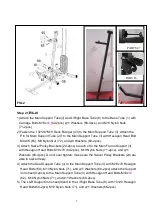
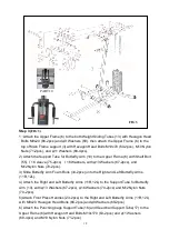
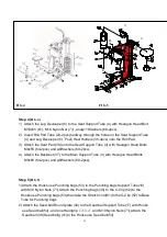
Step 6(
FIG .6)
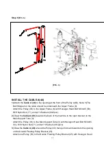
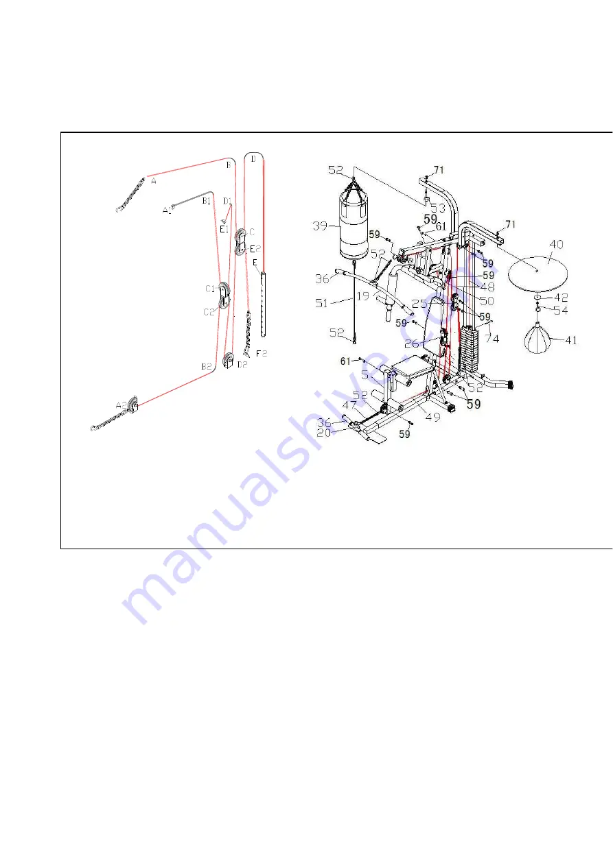
CABLE LOOP DIAGRAM
INSTALL THE CABLE A(48)
1)Attach the Cable A (48) to the opening at the front of the Pulley A(60). Note: 1)The
Ball Stopper on the cable should be underneath the Upper Frame (6).
Attach the Pulley (30) to the Upper Frame (6) with Hexagon Head Bolt M10x45 (59),
M10 Nylon Nut (71), and
φ
11 Washers (68-2pcs).
2) Draw the Cable A (48) towards the back of the machine to the open bracket on the
Main Support Tube (3).
Attach the Pulley (30) to the Main Support Tube (3) with Hexagon Head Bolt M10x65
(61), M10 Nylon Nut (71), and
φ
11 Washers (68-2pcs).
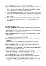
3) Draw the Cable A (48) around the Pulley (30) then pull it down towards to the opening
on the Double Floating Pulley Bracket (25).
Attach one Pulley (30) to the Double Floating Pulley Bracket (25) with Hexagon Head
(
FIG .6)
Summary of Contents for CD-2006A
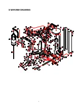
Page 4: ...3 OVERVIEW DRAWING...


