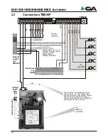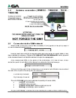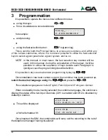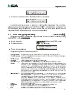
47
3.5
Channels
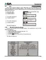
In this menu, it is possible to establish how the channels of the combiner must be
activated.
!
Key in the code:
(Default MASTER code)
!
Press the button:
(Programming)
!
Press the button:
(
Channels
)
!
This will be displayed
!
Press the button:
or
!
This will be displayed
!
Press the button:
or
!
This will be displayed
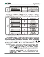
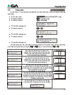
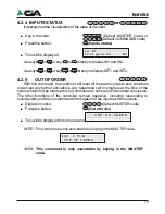
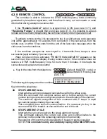
Choose between the activation mode depicted in the table under which condition
the channel is alarmed, using the
or
keys. Then press the
or
.
C H A N N E L
S E L E C T
C h a n n e l
1
_
C h a n n e l
1 - A c t i v a t i o n
1
1 - A c t i v a t i o n
N C
I m p u l s e
The channel is activated from the presence of a
positive 12Vcc to the input of the channel; the cycle
of calls comes started and carried out until the term,
if not interrupted through commandos..
The channel is activated from the absence of a
positive 12Vcc on the input of the channel; the cycle
of calls comes started and carried out until the term,
if not interrupted through commandos
The channel is activated from the presence
of a positive 12Vcc on the input of channel;il the cycle
of calls comes executed until the term if not interrupted
from a command or coming to lack
the positive one on the income
0
12V
Impulse NO
0
12V
Impulse NC
0
12V
Level NO
Level NC
0
12V
The channel is active to lacking the positive one 12Vcc
on the income of thechannel; the cycle of calls comes
activated and carriedout until the term, if not interrupted
through commandos or the restoration of the positive
one 12Vcc on the income
1 - A c t i v a t i o n
N o t
A c t i v e
_
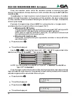
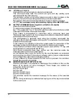
The active channel in no condition and on the first
one display of the combinatore is not come visualized:
I n i t G S M
C h 1 D i s a b l e d
Programmation
I n
K 1
N O
*
P l a y
#
R e c
I n
K 1
S I
*
P l a y
#
R e c
I n
K 2
N O
*
P l a y
#
R e c
I n
K 2
S I
*
P l a y
#
R e c
I N T 1
N O
*
P l a y
#
R e c
I N T 1
S I
*
P l a y
#
R e c
I N T 2
N O
*
P l a y
#
R e c
I N T 2
S I
*
P l a y
#
R e c
O u t
1
N O
*
P l a y
#
R e c
O u t
1
S I
*
P l a y
#
R e
O u t
2
N O
*
P l a y
#
R e c
O u t
2
S I
*
P l a y
#
R e c
Not active description for channel 1 input
Not presence voltage description for +12V on INT1
Not presence voltage descript12V su INT2
Not active description for out 1 output
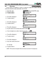
3.4
TXT/SMS
messages
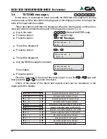
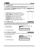
In this menu, it is possible to insert or modify the SMS that the combiner it sendes
in alarm case and the descriptions that appear on the display in order to indicate the
state of the input and the outputs.
These descriptions will then be displayed when the interrogation commands or
input and output commands are keyed on the keypad (see para 4.2.3).
!
Key in the code:
(Default MASTER code)
!
Press the button:
(Programming)
!
Press the button:
(
SMS Message
)
!
This will be displayed:
!
Press the button:
or
!
This will be displayed
!
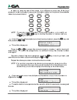
Key the SMS message to be stored
For exmaple:
!
Press the button:
Once the message to be stored has been keyed in, use the
or
keys and
then press the
or
key store the others.
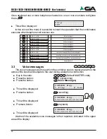
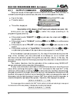
A table of the status of the inputs and outputs which can be visualized in the
upper part of the display:
C h a n n e l
C h .
1
1
C h a n n e l
C h . >
_
1
1
C h a n n e l 2
I r r i g a t i o n >
_
46
Active description for channel 1 input
Not active description for channel 2 input
Active description for channel 2 input
Presence voltage description for +12V on INT1
Presence voltage description for +12V on INT2
Active description for out 1 output
Not active description for out 2 output
Active description for out 2 output
TDC26-TDC36-TM26GSM-TM66GSM-ERMES2- User’s manual
1 - A c t i v a t i o n
N O
I m p u l s e
1 - A c t i v a t i o n
N C
I m p u l s e
1 - A c t i v a t i o n
N O
L e v e l
1 - A c t i v a t i o n
N C
L e v e l


