background image

31

Pipe installation

When doing the piping connection, please do the following:

• 

Please don't let the pipe and the parts in the unit collide each other.

• 

When connecting the pipes, close the valves fully.

•  Protect the pipe end against and water, impurities (welding after being flatted, or being sealed with adhesive 

tape).

• 

Bend the pipe as large semi-diameter as possible(over 4 times of the pipe diameter).

•  The connection between outdoor liquid pipe and the distributing pipe is flared type. Please expand the pipe with 

the special tool for R410A after installing the expanding nut. But if the projecting pipe length has been adjusted 

with the copper pipe gauge, you can use the original tool to expand the pipe.

• 

Since the unit is with R410A, the expanding oil is ester oil, not the mineral oil.

•  When doing the flare connection, please do the following: When connecting the expanding pipe, fasten the pipes 

with double-spanner. The torque refers to the former info.

• 

The outdoor gas pipe and the refrigerant distributing pipe, as well the refrigerant distributing pipe and the branch 

pipe should be welded with hard solder.

•  Weld the pipe at the same time charge the nitrogen. Or it will cause a number of impurity (a film of oxidation) to 

clog the capillary and the expansion valve, further cause the deadly failure.

•  Protect the pipe end against the water, impurity into the pipes (welding after being flat, or being sealed with 

adhesive tape).

•  The refrigerant pipe should be clean. The nitrogen should flow under the pressure of about 0.2Mpa and when 

charging the nitrogen, stop up the end of the pipe by hand to enhance the pressure in the pipe, then loose the 

hand (meanwhile stop up the other end).

• 

When connecting the pipes, close the valves fully.

• 

When welding the valve and the pipes, use  the wet cloth to cool down the valve and the pipes.

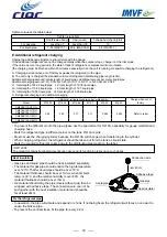
Pipe outer diameter

(mm)

 A 

Ø6.35

9.1

Ø9.52

13.2

Ø12.7

16.6

Ø15.88

19.7

Expanding pipe: A(mm)

Pipe outer diameter

(mm)

 When it is hard pipe 

Special tool 

for R410A

The former

tool

Ø6.35

0-0.5

1.0-1.5

Ø9.52
Ø12.7

Ø15.88

Projecting length of pipe to be expanded: B(mm)

Seal the pipe end with adhesive tape or the stopper to 

increase the resistance, fill up the pipe with nitrogen.

Only nitrogen gas 

can be used

Brazing

<N2>

Taping

Adhesive tape

Flat

Brazing

1st side

Hand

2nd side

Source valve

0.2MPa

Summary of Contents for CC43BV022LLYJ1H

Page 1: ...Version Mar 6th 2018...

Page 2: ...ng Diagram 16 6 Performance Curves 19 7 Operation Range 21 8 Noise Level 23 9 Outdoor Installation 24 9 1 Safety 24 9 2 Installation instruction 26 10 Electric Installation 34 11 Trial Operation 36 12...

Page 3: ...071 6YJ1H CK43BV090 6YJ1H CK43BV112 6YJ1H CK43BV126 6YJ1H CK43BV140 6YJ1H 2 WAY CASSETTE CK43BV022 2YJ1H CK43BV028 2YJ1H CK43BV036 2YJ1H CK43BV045 2YJ1H CK43BV056 2YJ1H 1 WAY CASSETTE CK43BV016 1YJ1H...

Page 4: ...280HHYJ1H CEILING FLOOR CF43BV028 MYJ1H CF43BV036 MYJ1H CF43BV045 MYJ1H CF43BV056 MYJ1H CF43BV071 MYJ1H CF43BV080 MYJ1H CF43BV090 MYJ1H CF43BV112 MYJ1H CF43BV140 MYJ1H CONSOLE CJ43BV022 MYJ1H CJ43BV02...

Page 5: ...frigerant ow realizes the linear output creates a comfortable environment The temperature could be controlled precisely Imprecise common control PID precise control Refrigerant ow speed Refrigerant ow...

Page 6: ...prompt than conventional control system Protections Pressure temp compressor fan motor refrigerant oil quantity etc Realize perfect performance Malfunction self diagnose 2 DC fan motor CM43BV140 HEJ1...

Page 7: ...LECTRIC Model TNB220FLHMC MNB42FFAMC L Type Rotary Rotary Compressor quantity 1 INV 1 INV Capacity W 7130 13780 Power input W 2200 4310 Rated current RLA A 9 7 15 8 Speed rps 60 60 Crankcase heater W...

Page 8: ...et weight kg 70 99 Gross weight kg 76 107 Refrigerant Type R410A R410A Charged volume kg 2 4 3 8 Throttle type EXV EXV Design pressure MPa 4 15 4 15 Refrigerant piping Liquid pipe mm 9 52 9 52 Gas pip...

Page 9: ...sor Brand MITSUBISHI ELECTRIC Model MNB42FFAMC L Type Rotary Compressor quantity 1 INV Capacity W 13780 Power input W 4310 Rated current RLA A 15 8 Speed rps 60 Crankcase heater W 28 Refrigerant oil b...

Page 10: ...Gross weight kg 107 Refrigerant Type R410A Charged volume kg 3 8 Throttle type EXV Design pressure MPa 4 15 Refrigerant piping Liquid pipe mm 9 52 Gas pipe mm 19 05 Total pipe length m 150 Max pipe l...

Page 11: ...del MNB42FFDMC L MNB42FFDMC L Type Rotary Rotary Compressor quantity 1 INV 1 INV Capacity W 13780 13780 Power input W 4060 4060 Rated current RLA A 12 3 12 3 Speed rps 60 60 Crankcase heater W 28 28 R...

Page 12: ...0 Net weight kg 99 99 Gross weight kg 107 107 Refrigerant Type R410A R410A Charged volume kg 3 8 3 8 Throttle type EXV EXV Design pressure MPa 4 15 4 15 Refrigerant piping Liquid pipe mm 9 52 9 52 Gas...

Page 13: ...11 Te Td Inverter compressor d s c e 4wv Gas pipe stop valve Condensor HP Tc Ts PMV SV1 Liquid pipe stop valve LP Ta Gas liquid separator 3 Refrigerant Circuit CM43BV110 HYJ1H...

Page 14: ...CM43BV140 HYJ1H CM43BV155 HYJ1H CM43BV140 HEJ1H CM43BV160 HEJ1H Td d s c e 4wv Ts PMV SV2 SV1 Gas pipe stop valve Liquid pipe stop valve HP LP Inverter compressor Gas liquid separator Condensor Ta Tc...

Page 15: ...rts up or stops AC220V SV2 Refrigerant jet protection when discharging temp is too high 4 way valve ALL 4WV Change over between cooling and heating AC220V electrified in heat not electrified in coolin...

Page 16: ...14 4 Dimension CM43BV110 HYJ1H 960 830 580 184 184 340 380 67 21 Drain hole...

Page 17: ...15 CM43BV140 HYJ1H CM43BV155 HYJ1H CM43BV140 HEJ1H CM43BV160 HEJ1H 960 1250 23 340 380 580 184 184 67 Drain hole Fixing hole 4 15...

Page 18: ...perature sensor ambient temp sensor electronic expend valve digital display tubes PC Monitor Tfin IPM temperature sensor BL R BL CN20 CN11 CN14 ACFAN1 M CN13 U P V W N AC N AC L LI LO CN11 REACTOR DC...

Page 19: ...ature sensor Symbol Signification thumbwheels WARING NOTES Please check the power firstly before test and make sure the crankcase heater powering on for 12 hours at least to protecting compressor Forb...

Page 20: ...ay board will display U indicates the number of Indoor units that the outdoor unit can communicate with If it can match the actual number of indoor units please change OFF to ON or else fix the commun...

Page 21: ...19 6 Performance Curves 1 Calculation method of refrigerating capacity Refrigerating capacity to be known Refrigerating capacity A B C D E W unit...

Page 22: ...wn Heating capacity A B C D E F W Outdoor modified capacity with a single indoor running outdoor modified capacity 3 Calculation method of refrigerating capacity Only one indoor unit running Outdoor m...

Page 23: ...5 20 25 30 35 40 45 50 55 Outdoor temperature C DB Indoor temperature C WB Continuous operation range Cooling Outdoor temperature C WB 10 20 15 20 25 30 1 5 1 0 Indoor temperature C DB Heating 5 0 5 1...

Page 24: ...perature C DB Indoor temperature C WB Continuous operation range Cooling Outdoor temperature C WB 10 20 15 20 25 30 15 10 Indoor temperature C DB Heating 5 0 5 10 15 20 Continuous operation range 25 2...

Page 25: ...continuous noise NC 60 NC 50 NC 40 NC 30 NC 20 H 8000 4000 2000 1000 500 250 125 63 63 63 63 63 63 63 63 70 60 50 40 30 20 10 Octave band center frequency Hz Octave band sound pressure level dB A Lim...

Page 26: ...appliances are not intended to be operated by means of an external timer or separate remote control system Keep the appliance and its cord out of reach of children less than 8 years WARNING The insta...

Page 27: ...and exceeds the limited concentration it will cause lack of oxygen Don t use the other refrigerant except for R410A The R410A pressure is 1 6 times higher than R22 pressure The refrigerant R410A tank...

Page 28: ...wires and parts purchased respectively are correct 2 Check if the indoors and outdoors can be combined as the following Notice Total capacities of indoor units being used 100 of rated capacities of ou...

Page 29: ...hole at bottom of the unit When being hanged the rope should be 4 pieces of steel cable with over 6mm diameter Put the cushion at the contact section between steel cable and the unit against the dist...

Page 30: ...er pipe should be performed according to the relative manual Pipe specification a a a a b b c 1 Pipe a diameter between indoor and branch pipe depends on indoor pipe Please refer to the indoor air con...

Page 31: ...L 40m L2 L3 L4 e Drop height Drop height between indoor and outdoor unit H Up outdoor 30m Under outdoor 20m Drop height between indoor units h 10m CM43BV110 HYJ1H type Maximal length and drop height p...

Page 32: ...re than 1 4 Branch pipe Outdoor unit type Branch pipe selection Note 1 When connecting the pipe and the outdoor please pay attention to the outdoor pipe dimension 2 When adjusting the diameter among p...

Page 33: ...ipe and the branch pipe should be welded with hard solder Weld the pipe at the same time charge the nitrogen Or it will cause a number of impurity a film of oxidation to clog the capillary and the exp...

Page 34: ...sition by laying on the soap modify the leakage point and take another leakage test 4 After leakage test must execute the evacuation Evacute at the check valve of liquid stop valve and both sides of t...

Page 35: ...charging refrigerant the refrigerant should be taken out from the tank as liquid state Mark the counted refrigerant volume due to the distributing pipe length on the label Tighten torque as the table...

Page 36: ...r and master indoor are connected by 3 polar wires When indoor is controlled by remote controller refer to the wired control master unit wired control slave unit remote control unit table A B C on sig...

Page 37: ...ength m Rated current of overcurrent breaker A Rated current of residual circuit breaker A Ground fault interrupter mA response time S Communication wire section Outdoor indoor mm2 Indoor indoor mm2 1...

Page 38: ...g mode air outlet and air inlet of outdoor are clogged In heating mode indoor filter is stacked with duct indoor air outlet is clogged When protection device acts please cut off the power source and r...

Page 39: ...onfirm the compressor bottom getting hot Except for the condition that there is only one master unit connected no slave unit under the other conditions open fully the outdoor operating valves gas side...

Page 40: ...38 12 PCB Photo...

Page 41: ...l AC default ON All DC BM1_4 Energy saving or refrigeration effect priority 4 Energy saving or refrigeration effect priority OFF Energy saving priority ON Refrigeration effect priority BM1_5 Indoor si...

Page 42: ...ce selected 5 Power source selected OFF Single phase ON Three phase BM2_7 BM2_8 Running mode preference 7 8 Running mode preference OFF OFF Start first default OFF ON Later start first ON OFF Cooling...

Page 43: ...uency control Up Down to adjust the frequency press Stop 5 seconds to exit manual frequency control Frequency flashes when manual control while non manual control frequency displays normally 5 Actual...

Page 44: ...ndoor unit types 0 Ordinary indoor uint 1 Wall mounted 2 Fresh air uint 3 Heat reclaim ventalation 4 7 Ordinary indoor unit 4 0 F Display failure code when suffers failure or else display 5 0 F Indoor...

Page 45: ...ue 2 Tao 5 C In order to improve the effect of indoor unit reach the purpose of rapid cooling heating make the following control 1 In cooling when outdoor ambient temperature above 25 C the first 60 m...

Page 46: ...ously Outdoor Te 20 C for 30s continuously Outdoor Te 30 C for 5s continuously Tc 54 C OR OR After heating startup 60min C 23 Tao 15 C Te Tao 69 4 For 5min continuously D Tao 23 C Te 23 C For 5min con...

Page 47: ...ening angle increased 10 max time is 2 When Td 90 C returns to the usually opening OR 15 4 Oil return control 15 4 1 Entering condition 15 4 2 Oil return control 15 4 3 Oil return quit condition OR OR...

Page 48: ...he searched indoor quantity is more than the set quantity 30 1E High pressure switch HPS failure If disconnect for 50ms continuously alarm If alarm 3 times in an hour confirm the failure Once confirma...

Page 49: ...firmation un resumable 82 52 Compressor current protection Compressor current exceeds specified value 3 minutes after recovery 108 6C Transient over current in IPM module rectifier side software Trans...

Page 50: ...abnormal Current detection sensor of frequency controller is abnormal or unconnected or connected wrongly 120 78 Power supply of transducer abnormal Power supply of transducer is broken down instantl...

Page 51: ...ture sensor failure If sensor terminal is fixed well If voltage between red terminal and black terminal is 5V when testing pressure sensor by multimeter If voltage between white terminal and black ter...

Page 52: ...lure disappears after changing indoor PCB If there is noise source Check outdoor PCB if faulty replace it If communication wire is separate from high voltage wire on layout Modify the communication wi...

Page 53: ...6MPa Replace 4 way valve Re connect Check if SV1 leaks Replace connecting board Check compressor Measure if CN49 voltage on connecting board is 220VAC after 4 way valve reversing condition is met If t...

Page 54: ...ogged Make pressure switch terminal on connecting board in short circuit check if failure exists still If sensor resistor characteristic is proper If sensor terminal is fixed well If the system is lac...

Page 55: ...fixed well Check if refrigerant is too much In cooling mode when the indoor unit off if the EEV can t completely close Fix again or replace the sensor Reconnect Replace or adjustment the indoor unit E...

Page 56: ...e is in conformance with the measured data by sensor Check if terminal of electronic expansion valve coil is fixed well Check if piping system is clogged Check if system is lack of refrigerant Check i...

Page 57: ...runs normally If stop valve opens fully If in heating indoor fan motor runs normally and if filter is clogged Check if piping system is clogged No No No No Yes Yes Yes Yes Yes Replace pressure sensor...

Page 58: ...fixed well Check if refrigerant is too much In cooling mode when the indoor unit off if the EEV can t completely close No No No Yes Yes Yes Yes Re connect Replace module Replace wire Replace connectin...

Page 59: ...check if failure exists still Replace pressure switch Replace connecting board Re connect No Yes No No Yes Yes If the system lack of refrigerant Recharge the refrigerant 53 Current sensor failure Chec...

Page 60: ...f temperature on top of fixed fixed frequency compressor is too high If normal after replacing CT detector If AC contactor work If there is air into the system If there is clogged motor is bad Replace...

Page 61: ...ously fiction Forced the fan in low speed measure if it has alternating voltage between FG and GND Check the motor and PCB connection is well Replace fan motor Re connect Replace the motor Replace the...

Page 62: ...d oppositely If 4 way valve is interconnected Measure if there is voltage U V W of compressor by multimeter and if it is normal Replace inverter compressor Re connect Correct compressor wire Correct c...

Page 63: ...balance Check if the high low pressure is normal Change the module Reconnect or change the wires Change the compressor Yes Yes Yes No No 82 Compressor current protection 108 Transient over current in...

Page 64: ...move the failure Solve the failures due to relative information If power module is normal Check if wire of electric box is correct and if compressor wire is fixed well If there are the other failure r...

Page 65: ...ressor are normal If compressor is normal compressor coil resistor insulation Compressor load too much check the reason Check the temperature sensor characteristic is correct Check the radiator is blo...

Page 66: ...Protection of overload 114 Voltage too low of DC bus line of transducer Check if voltage of power supply is normal Measure if DC bus line voltage between P and N of module is less than 375V Circuit of...

Page 67: ...power supply circuit Correct the wiring due to diagram Circuit of DC bus line voltage on inverter control board abnormal replace inverter control board Yes Yes Yes No No No Check if wire between cont...

Page 68: ...power module If compressor is normal compressor coil resistor insulation Yes Yes Yes Yes No No No No 117 Transducer over current software protection 118 Compressor startup failure Check if voltage of...

Page 69: ...direction of DCCT is normal Check if current sensor is normal Replace inverter PCB Correct the wiring due to diagram Replace current sensor No No Check if connection between temp sensor and inverter...

Page 70: ...cuit DC bus line voltage circuit on inverter board broken down replace inverter module board Adjust or replace relay or AC contactor Correct the wiring due to diagram Improve power supply circuit Yes...

Page 71: ...56 23 103 00 96 72 90 44 6 49 6 49 22 97 85 91 95 86 05 6 42 6 42 21 92 92 87 37 81 83 6 35 6 35 20 88 20 82 99 77 79 6 27 6 27 19 83 70 78 82 73 93 6 20 6 20 18 79 42 74 83 70 25 6 13 6 13 17 75 34 7...

Page 72: ...9 29 8 80 8 52 8 24 3 25 3 25 30 8 46 8 19 7 92 3 31 3 31 31 8 14 7 87 7 61 3 38 3 38 32 7 83 7 57 7 31 3 44 3 44 33 7 53 7 28 7 02 3 50 3 50 34 7 25 7 00 6 75 3 56 3 56 35 6 98 6 73 6 49 3 63 3 63 36...

Page 73: ...35 6 38 6 38 80 1 49 1 40 1 31 6 44 6 44 81 1 44 1 36 1 27 6 50 6 50 82 1 40 1 32 1 23 6 56 6 56 83 1 36 1 28 1 19 6 63 6 63 84 1 32 1 24 1 16 6 69 6 69 85 1 29 1 20 1 12 6 75 6 75 86 1 25 1 17 1 09...

Page 74: ...171 01 164 40 157 79 4 02 4 02 11 161 13 154 98 148 84 3 96 3 96 10 151 87 146 15 140 44 3 91 3 91 9 143 18 137 87 132 56 3 85 3 85 8 135 04 130 10 125 15 3 80 3 80 7 127 40 122 80 118 20 3 75 3 75 6...

Page 75: ...48 2 48 37 13 70 13 36 13 03 2 53 2 53 38 13 12 12 79 12 47 2 57 2 57 39 12 57 12 25 11 93 2 61 2 61 40 12 05 11 74 11 42 2 66 2 66 41 11 55 11 24 10 94 2 70 2 70 42 11 07 10 78 10 48 2 74 2 74 43 10...

Page 76: ...2 34 4 45 4 45 82 2 47 2 37 2 26 4 49 4 49 83 2 39 2 29 2 19 4 54 4 54 84 2 32 2 22 2 12 4 58 4 58 85 2 25 2 15 2 05 4 63 4 63 86 2 18 2 08 1 98 4 67 4 67 87 2 11 2 02 1 92 4 71 4 71 88 2 05 1 95 1 86...

Page 77: ...65 19 635 89 688 00 740 12 7 58 7 58 20 605 19 654 25 703 32 7 50 7 50 21 576 15 622 36 668 57 7 43 7 43 22 548 66 592 19 635 72 7 35 7 35 23 522 65 563 65 604 66 7 28 7 28 24 498 01 536 64 575 28 7 2...

Page 78: ...51 81 76 85 01 3 98 3 98 68 75 57 78 64 81 70 3 90 3 90 69 72 75 75 65 78 54 3 83 3 83 70 70 05 72 78 75 51 3 75 3 75 71 67 47 70 04 72 61 3 68 3 68 72 64 99 67 42 69 84 3 60 3 60 73 62 61 64 90 67 1...

Page 79: ...114 14 93 15 76 16 59 5 27 5 27 115 14 46 15 28 16 09 5 33 5 33 116 14 01 14 80 15 60 5 40 5 40 117 13 57 14 35 15 13 5 47 5 47 118 13 14 13 91 14 68 5 53 5 53 119 12 73 13 49 14 24 5 60 5 60 120 12 3...

Page 80: ...0 2 7 1 5 2 2 2 9 1 7 2 4 3 1 1 8 2 5 3 2 3 3 0 8 2 0 1 0 0 1 0 2 0 3 0 4 0 5 0 6 0 7 0 8 0 9 0 1 0 0 1 1 0 1 3 0 1 2 0 k k g k c a l k g 0 5 10 15 20 25 30 35 40 i d k kg kcal kg Wet air enthalpy hum...

Page 81: ...CARRIER INTERAMERICA CORPORATION MIAMI FLORIDA USA C CIAC 2018...

Reviews: