CIAS Elettronica S.r.l.
Ed. 1.2
Installation Manual
Page 33 of 36
NEWTON-L
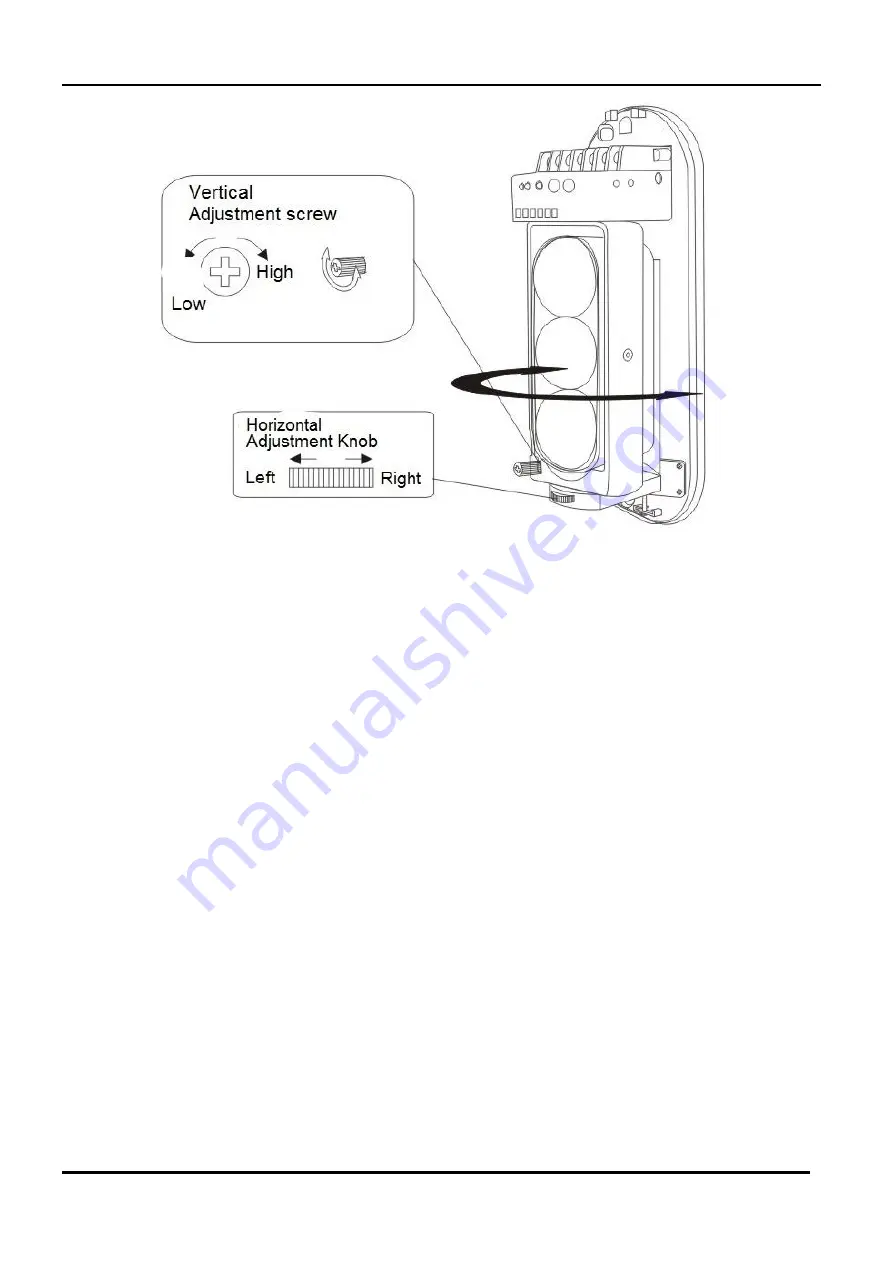
15. ALIGNMENT USING DIGITS
Alignment quality is shown by the value of the digit on the two-digit display (Digit). Higher is the
number displayed (range from 0.0 to 3.3), better is the alignment obtained. Make adjustments
until you reach the highest value possible.
The implementation of good alignment is equivalent to higher signal quality and thus to better
system stability.
All adjustments must be made on both optics, transmitter and receiver, starting from the latter to
then pass to the transmitter. Finally, re-tune alignment on the optical receiver.
NOTE: When multiple transmitters are facing as many receivers (multiple installation), before
proceeding with the alignment of each pair, cut off power or cover the transmitter parts not
involved in alignment with adequate thickness obscuring screens. This precaution allows you to
align the first transmitter on its receiver and so forth for all other optics.
An additional check must be made at the end to verify the overall alignment of the optics,
making sure that no other infrared signal is detected by the individual receiver module in the
case in which its own transmitter is obscured. To do so, obscure all transmitting parts and verify
that the voltage read on the Digit is close to a value of zero. This check detects that no other
infrared source is acting on that receiver and, as a result, no other external signal is adversely
influencing the operation of equipment. In the case of multiple installation, make sure that the
level of the signal not generated by each own infrared transmitter and received by each
individual receiving optic is lower than a value of at least 0.5 (Digit) with respect to the signal
level detected by the corresponding transmitter.
Summary of Contents for NEWTON-L
Page 38: ...NOTE...
Page 39: ...NOTE...


