CIAS Elettronica S.r.l.
Ed. 1.2
Installation Handbook
Page
71
of
73
ERMO 482X3
PRO
5 MAINTENANCE AND ASSISTANCE
5.1 Troubleshooting
In case of false alarm, check the parameters recorded during the
Installation
phase (on
attached
Test Sheet
), if there are divergences with permitted limits check again the related
points in chapter "Adjustment and Testing (4)"
Defect
Possible Cause
Possible Solution
Main Power supply LED off Tx
and/or Rx
Power Supply
19 V~ or 24V
missing
Check out the Primary and Secondary
power supply of the Transformer
Connections broken
Ad just the connections
Power Supply circuit broken
Change the Electronic board
Fault Led OFF
Power too high or too low
Check the battery voltage and the
power supply
Temperature too high or too low
Check the temperature of the barrier
Tx Oscillator Fault
Change the Oscillator
Tx or Rx failures
Change the Electronic board
Alarm Led OFF
Movement or obstacles in the
protected field
Check out that the protected field is
free from obstacles and free from
objects and/or person moving.
Barrier not properly aligned
Re do the alignment procedure as
described in points: a,b,c,d,e,f,g,h,i of
charter 4.1.2
Wrong channel selections
Do again the Channel acknowledge
procedure as described in point j of
charter 4.1.2
Alarm of sensor connected on the
balanced line input.
Check out the sensor connected to
the balanced line input. If no sensors
are connected, disable balanced line.
(For TX close JP4, for RX see chapter
4.1.2, point u)
High AGC Voltage
Barrier not properly aligned
Re do the alignment procedure as
described in points: a,b,c,d,e,f,g,h,i of
charter 4.1.2
obstacles in the protected field
Remove obstacles
Too low signal transmitted
Check the transmitter
Rx circuit fault
Change the Rx circuit
Rx MW part fault
Change the RX MW part
Tamper Led OFF
Micro switch open
Check the micro switch position
Tilt bulb in wrong position
Check the position of the tilt bulb
Fault Led Off only on TX circuit
BF Oscillator Fault
Change the TX circuit
MW oscillator Fault
Change the MW part
5.2 Maintenance kits
The
Maintenance Kits
are composed by circuits equipped with microwave cavities, their
substitution is very easy:
Unlock the only one fixing screw and install the new circuit into related plastic guides present on
the bottom box.
The circuit and cavity substitution, on both transmitter and receiver heads
, doesn’t
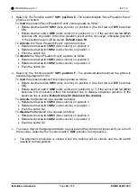
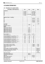
change the heads alignment, and so no new alignment is required.

