©
CIAS Elettronica S.r.l.
Ed 1.1
Installation Manual
Page
37
of
51
Sioux Pro 2
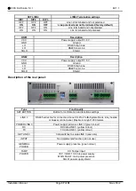
SET LINE2
LINE2 Termination settings
DIP1
DIP2
DIP3
OFF
OFF
OFF
Line not terminated and not polarised
ON
ON
OFF
Line polarised and not terminated (factory default)
OFF
OFF
ON
Line terminated and not polarised
ON
ON
ON
Line terminated and polarised
LINE1
Description
VCC
Power supply output:13.8 V
GND
Ground
LH
RS485 High Line
LO
RS485 Low Line
SHLD
Shield
LINE2
Description
VCC
Power supply output:13.8 V
GND
Ground
LH
RS485 High Line
LO
RS485 Low Line
SHLD
Shield
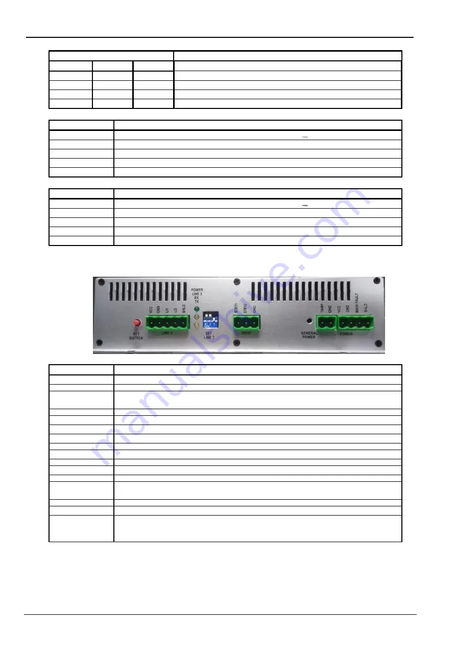
Description of the rear panel:
Type
Functionality
SET BUTTON
Button for confirmation and functions settings
LINE 3
RS485 serial line for connection Sioux-CU-Pro2 to IB-System-Rack, relay boards
or Quasar control panel. Maximum lenght 1200 meters.
POWER LINE 3
Power supply presence LINE 3 (green colour)
RX
RX data LINE 3 (yellow colour)
TX
TX data LINE 3 (yellow colour)
SET LINE 3
3 dip switches to setup LINE 3 (see note)
INPUT
Not implemented function (do not use)
GENERAL
POWER
Power supply presence (green colour)
TAMP
CU Tamper input
POWER
VCC / GND: 13,8 Vdc power supply
MAIN FAULT: main power presence
SHLD: power supply shield

