EN-
37
POWERCIAT LX ST/HE/XE
8 - HEAT RECOVERY CONDENSER OPTION
8.1 - Physical properties, LX units with heat recovery condenser option
LX ST/HE/XE heat reclaim mode
0808
0908
1008
1108
1358
1528
1858
2008
2158
2308
2528
2628
3028
Operating weight
(1)
kg
3370
3404
3425
4102
4245
4601
5551
5782
6065
6382
6430
6805
7272
Condenser diameter
inches
10
10
10
12
14
14
12+12 12+12 14+12 14+12 14+12 14+14 14+14
Refrigerant charge
Circuit A
kg
37
35
35
51
52
59
58
58
65
69
72
69
91
Circuit B
kg
39
37
37
37
37
36
59
62
58
65
63
76
89
Heat reclaim condenser
Flooded multi-pipe condenser
Water volume
l
38
38
38
55
68
68
55+55 55+55 68+55 68+55 68+55 68+68 68+68
Water connections
Type Victaulic
Nominal diameter
inches
3
3
3
4
4
4
4
4
4
4
4
4
4
Actual outside diameter
mm
88,9
88,9
88,9
114,3 114,3 114,3 114,3 114,3 114,3 114,3 114,3 114,3 114,3
(1) Weights are for guidance only
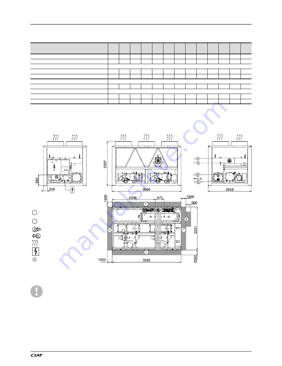
8.2 - Dimensions and clearances
8.2.1 - LX 0808 to 1008 - heat recovery option
The condenser connection sleeves are not installed,
but supplied with the unit. The sealing gaskets are
in the electrics box. The temperature sensors and
the condenser flow switch are wired and fixed in the
machine. They must be installed as described in the
chapter “Condenser water connections”.
NOTES:
•
Drawings are not contractually binding.
•
Before designing an installation, consult the certified
dimensional drawings, available on request.
•
For the positioning of the fixing points, weight distribution
and centre of gravity coordinates please refer to the
dimensional drawings.
• If the installation includes several units or if this (these)
is (are) close to walls, please refer to chapters 3.11
“Multiple chiller installation” and 3.12 - “Distance to the
wall” of this document to determine the space required.
Key
All dimensions are given in mm.
1
Required clearances for maintenance
(see note)
2
Recommended space for evaporator tube
removal
Water inlet for standard unit
Water outlet
Air outlet – do not obstruct
Power supply and control connection
A
Heat reclaim condenser


