


EN - 7
E N
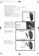
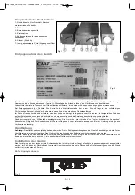
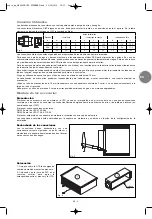
Damper rotation control
The damper has a 90° rotation angle.
Manual control :
standard mounting
This manual control is fitted on the left (standard mounting).
It can be dismounted and fitted on the right (fixation with
3 sheet metal screws).
Motorisable control :
delivered with the box mounting kit
After dismounting the standard manual control (fixed by 3
sheet metal screws), put in place the motorisable control
delivered in the plastic bag.
The fixation of this control is made by tightening onto the
dampers axis (M6 x 40 w screw).
Actuator :
optional (consult our technical department)
Actuator with return spring, return to zero through lack of
current, stop for damper rotation angle control.
Not wired - 230 / 1 / 50.
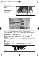
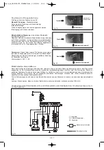
Electrical connections
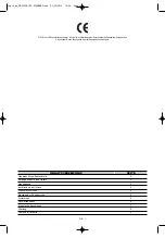
Before connecting the unit to the mains, make sure that the voltage is the same as that indicated on the unit identification plate.
The connections to the mains should comply with the applicable installation regulations. The unit must be earthed. We cannot be
held responsible for accidents following incorrect or non-existent earthing.
With appliances featuring optional electronic components, comply with the electrical diagram supplied with the appliance.
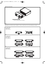
For customer applications, the electrical diagram is to be drawn up from the generic diagrams provided below.
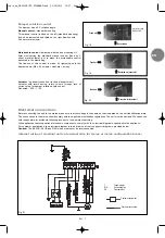
Caution:
The BLACK, BLUE and RED wirds must never be interconnected.
Internal wiring of standard unit on terminal strip for 2-pipe or 4-pipe configuration tubes:
Fig. 18
Fig. 19
Fig. 20
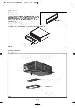
Control lever with
locking screw
Recycled air
Recycled air (eventual)
Recycled air (eventual)
Fresh air
Fresh air
Fresh air
F :
Fused isolator
MK :
Air handling fan
XB :
Terminal block
Customer equipment
Customer connection
Fig. 21
copie_de_NA0033B UTA STANDARD.qxd 31/05/2010 15:07 Page 7


