background image

X-treme Brush Cutter

January 2021

33

4.8    Gearbox Motor Maintenance

Maintenance procedures for the gear box motor require special tools 
and skills. DO NOT attempt to service the gear box motor unless you 
have the tools and skills to do so. Take your brush cutter to your local 
dealer to have the gear box motor serviced.

1. 

CHECK the oil level by removing the oil filler plug. The oil level 

should be at mid height of the input spline. 

2.  If low, add 

85W-140 5EP

 grade gear oil. Be sure to check the gear 

box oil weekly.

The initial oil should be changed after 50 hours of operation under load. 
Subsequent oil changes should take place after every 1000 hours of 
operation.

Checking Fluid Level

Oil Level

Oil filler plug

Summary of Contents for X-TREME XBC60LF

Page 1: ...NCE PROCEDURES XBCLFMFMAN01 JANUARY 2021 O W N E R S M A N UA L MT Mulching Teeth X TREME BRUSH CUTTER 30 48 GPM 30 48 GPM MODEL SERIES 20 30 GPM 20 30 GPM XBC60MF XBC72LF XBC78LF XBC78MF XBC60LF XBC7...

Page 2: ...DEALER INFORMATION PURCHASE DATE DEALER NAME ADDRESS PHONE NUMBER Record product information below...

Page 3: ...FIRST EDITION JANUARY 2021 Register this product at www cidattachments com MODEL COMPARISON X treme Brush Cutter Low Flow 14 20 gpm 3 blades 100HP right angle gear box 6 cut capacity Optional mulchin...

Page 4: ...TABLE OF CONTENTS...

Page 5: ...NANCE PROCEDURES 4 1 Maintenance Overview 26 4 2 Maintenance Schedule 27 4 3 Storage Tips 28 4 4 Blade Holder Removal 28 29 4 5 Blade Holder Installation 30 4 6 Blade Removal Procedures 30 31 4 7 Blad...

Page 6: ...e X treme Brush Cutter All users must read and understand this manual before operating this machine Upon reading this manual all users should sign the Safety Acknowledgement Form at the end of this ma...

Page 7: ...SAFETY INFORMATION SECTION 2 7...

Page 8: ...NOWLEDGE your understanding of all safey instructions presented in this manual by signing the Safety Acknowledgement Form at the end of this manual 8 X treme Brush Cutter implement attachment product...

Page 9: ...DANGER WARNING or CAUTION Indicates a potentially hazardous situation which if not avoided could result in death or serious injury Indicates a potentially hazardous situation which if not avoided may...

Page 10: ...rs and Maintenance personnel must wear proper eye protection and use cardboard or wood to investigate hydraulic leaks to prevent death or serious injury from being injected with high pressure hydrauli...

Page 11: ...this machine are in place to keep you safe DO NOT ignore these decals Read and understand each decal s safety message The following safety decals are affixed to this machine 11 21 31 41 SCAN TO VIEW...

Page 12: ...Figure 2 3 Safety Decal Locations 12 21 11 41 3...

Page 13: ...al Locations Cont 13 Decals must be kept clean and legible at all times Operators must inspect the machine for safety decals Replace missing worn or damaged decals immediately Use care when cleaning t...

Page 14: ...sult in minor or serious injury 14 The X treme Brush Cutter should only be used on Skid Steer Loader s that meet the following requirements Minimum Lift Capacity 2 200 lb Minimum Weight w Bucket Remov...

Page 15: ...play on or around this equipment at any time Store this implement in an area not frequented by children ALWAYS wear the proper personal protection equipment while operating or servicing this machine...

Page 16: ...X treme Brush Cutter January 2021 16 OPERATING PROCEDURES SECTION 3...

Page 17: ...e brush cutter attachment plate is flat against the skid steer quick attach mechanism see figure 3 2a below Consult your skid steer operator s manual for specific instructions on how to connect your b...

Page 18: ...thrown at the operator Check that hydraulic hoses are locked into the skid steer couplers before starting the cutter To keep contaminants from entering the hydraulic system wipe off any dirt or dust f...

Page 19: ...g the Cutter Your brush cutter is designed to run off the skid steer loader s auxiliary hydraulic system and is activated and deactivated by a control in the operator s cab The height and tilt functio...

Page 20: ...If the brush cutter begins to vibrate while increasing the RPM s deactivate the auxilary hydraulic system and investigate the cause Refer to the Troubleshooting Chart on page 36 of this manual Stoppin...

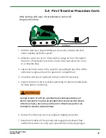
Page 21: ...d exit the operator s compartment 4 Check the skid steer s hydraulic oil level add oil if necessary 5 Inspect the brush cutter hydraulic plumbing for any noticeable leaks Fix leaks before continuing 6...

Page 22: ...on page 36 of this manual ALWAYS be aware of your surroundings and pay attention to what obstacles and terrain are in front of you Use the skid steer loader s lift and tilt controls to adjust brush cu...

Page 23: ...and mark any utilities steel posts rocks or any other objects that could damage the brush cutter during operation NEVER assume the work area is safe 2 Operate the skid steer loader at a safe speed th...

Page 24: ...wn reduce your travel speed and allow the cutter to reach the proper rotating speed Mowing TOO fast in thick vegetation could result in balling of the material underneath the cutter deck resulting in...

Page 25: ...X treme Brush Cutter January 2021 25 MAINTENANCE PROCEDURES SECTION 4...

Page 26: ...ey the following safety instructions when servicing or repairing this machine Wear proper Personal Protective Equipment PPE while working on this machine which may include safety glasses hard hats ste...

Page 27: ...sing Change oil after 50 hours of first time use then every 1000 hrs or yearly Wash Brush Cutter x Check brush cutter for major scratches and dings Sand and repaint these areas to prevent rust damage...

Page 28: ...injured by the unexpected rolling or movement of the skid steer ALWAYS release the hydraulic system pressure from the auxilary hydraulic circuit prior to removing the blade holder 4 3 Storage Storage...

Page 29: ...d CHOCK skid steer tracks tires to prevent skid steer from moving 4 SECURE the front end of the cutter deck with an overhead hoist and chain If you are performing this procedure in the field lean the...

Page 30: ...shown in the Torque Table on page 34 Blade Removal Procedure 1 Remove the blade holder as described in Section 4 4 of this manual 2 Carefully cut the welded bead around the bolt head to allow the bolt...

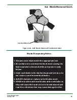
Page 31: ...nd each blade to the similar shape and size so as to not create a set of mismatched blades 4 ALWAYS sharpen or replace cutter blades as set 5 NEVER mix and match used blades with new blades as they wi...

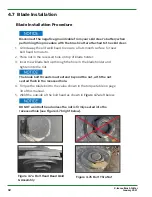
Page 32: ...en into the nut 4 Torque the blade bolt to the value shown in the torque table on page 34 of this manual 5 Weld the outside of the bolt head as shown in Figure 4 7a left below The blade bolt threads m...

Page 33: ...cutter to your local dealer to have the gear box motor serviced 1 CHECK the oil level by removing the oil filler plug The oil level should be at mid height of the input spline 2 If low add 85W 140 5EP...

Page 34: ...tion Table 4 8 Gear Box Motor Maintenance Cont 1 Remove oil filler plug 2 Insert one end of a discharge hose into the gear box oil fill port and the other end into an approved waste oil container 3 Pu...

Page 35: ...X treme Brush Cutter January 2021 35 TROUBLESHOOTING SECTION 5...

Page 36: ...utting height too low for cutting in sandy or rocky soils Raise cutter height Blades get dull too quickly Blades have contacted solid objects rocks steel pipes etc Clear cutting area of solid objects...

Page 37: ...X treme Brush Cutter January 2021 37 SPECIFICATIONS SECTION 6...

Page 38: ...d Steer Extreme Brush Cutter 72 no case drain XBC72LF 1 650 6 500 2 200 65 HP 85W 140 5EP 6 3 3 16 or 1 4 y Skid Steer Extreme Brush Cutter 78 no case drain XBC78LF 1 660 6 500 2 200 65 HP 85W 140 5EP...

Page 39: ...X treme Brush Cutter January 2021 39 PARTS INFORMATION SECTION 7...

Page 40: ...u receive the correct parts for your implement please provide your dealer with the following information Model Number Serial Number GPM Requirements Date of Owners Manual Bottom Left Corner of Cover P...

Page 41: ...n Coupling Gear Set 1 5 Bolt Set Gearbox to Deck 1 6 Elbow Motor Hydraulic 1 7 Hydraulic Motor 1 8 Hose Motor to Tee 1 9 Tee 2 10 H Valve 1 11 Hose Tee to Quick Disconnect 2 12 Blade Holder 1 12 Mount...

Page 42: ...n Coupling Gear Set 1 5 Bolt Set Gearbox to Deck 1 6 Elbow Motor Hydraulic 1 7 Hydraulic Motor 1 8 Hose Motor to Tee 1 9 Tee 2 10 H Valve 1 11 Hose Tee to Quick Disconnect 2 12 Blade Holder 1 12 Mount...

Page 43: ...X treme Brush Cutter January 2021 43 7 1 Parts Diagrams This page intentionally left blank...

Page 44: ...X treme Brush Cutter January 2021 44 WARRANTY INFORMATION SECTION 8...

Page 45: ...all be solely limited to repairing or replacing any part see non covered items above free of charge that according to our judgment show evidence of a defect in quality of workmanship or materials for...

Page 46: ...the model and serial number of the defective item s a description of the problem and have photographs available 2 Upon a warranted issue visit www cidattachments com click on the warranty tab and fil...

Page 47: ...ATTN ALL OPERATORS Print your name sign and date in the boxes below to acknowledge that you have read and fully understand the safety instructions presented in this manual and have been trained on ho...

Page 48: ...TENTION ALL OPERATORS Print your name sign and date in the boxes below to acknowledge that you have read and fully understand the safety instructions presented in this manual and have been trained on...

Page 49: ...X treme Brush Cutter January 2021 49 MAINTENANCE LOG SECTION 9...

Page 50: ...X treme Brush Cutter January 2021 50 MAINTENANCE LOG Use this log sheet to document all routine maintenance and repair services performed on this machine DESCRIPTION OF MAINTENANCE DATE SERVICED BY...

Page 51: ...NORTH CAROLINA DENTON...

Page 52: ...1248 N Main Street P O Box 1230 Denton NC 27239 Phone 336 859 2002 Fax 336 859 0800 sales cidattachments com www cidattachments com...

Reviews: