SERVICE MANUAL
Transmig 165
ST
Transmig 165
ST
SERVICE MANUAL
Transmig 165
ST
Transmig 165
ST
Manual 0-5442
11-7 DISASSEMBLY PROCEDURE
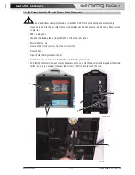
11.06 Power Switch S1 and Power Cord Removal
!
Read and follow safety information in Section 10.02 before proceeding with disassembly
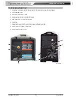
1. Gas hose is fixed to the gas inlet nipple using a metal gas line hose clamp (gas hose has been remove
in picture).
2. SW1 locking tabs
Squeeze the locking tabs and push SW1 out from the rear panel.
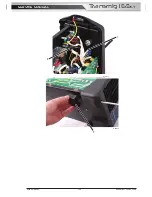
3. Strain relief screws
Remove the two (2) screws from the strain relief.
4. Remove Fan.
5 Input Power Cord ground wire filter.
Cut the tie-wrap and remove the Ferrite core from the ground wire.
6. Pull the Input Power Cord out. It may be necessary to use a flat blade screw driver against the strain
relief tabs, prying outward (Internal side if strain relief) to help remove the cord.
1
4
5
Art # A-12988
3
A_10006
6
2
Summary of Contents for Transmig 165ST
Page 16: ...SERVICE MANUAL Transmig 165ST Transmig 165ST GENERAL INFORMATION 1 10 Manual 0 5442 Notes ...
Page 32: ...OPERATION 4 6 Manual 0 5442 SERVICE MANUAL Transmig 165ST Transmig 165ST Notes ...
Page 84: ...SERVICE MANUAL Transmig 165ST Transmig 165ST THEORY OF OPERATION 9 2 Manual 0 5442 Notes ...
Page 120: ...SERVICE MANUAL Transmig 165ST Transmig 165ST ASSEMBLY PROCEDURE 12 8 Manual 0 5442 Notes ...
Page 125: ...SERVICE MANUAL Transmig 165ST Transmig 165ST This Page Intentionally Blank ...

