SERVICE MANUAL
Transmig 165
ST
Transmig 165
ST
SERVICE MANUAL
Transmig 165
ST
Transmig 165
ST
Manual 0-5442 5-7
MIG (GMAW) WELDING
5.06 Feed Roller Pressure Adjustment
The pressure (top) roller applies pressure to the grooved feed roller via an adjustable pressure screw. These
devices should be adjusted to a minimum pressure that will provide satisfactory WIREFEED without slippage. If
slipping occurs, and inspection of the wire contact tip reveals no wear, distortion or burn back jam, the conduit
liner should be checked for kinks and clogging by metal flakes and swarf. If it is not the cause of slipping, the
feed roll pressure can be increased by rotating the pressure screw clockwise.
!
WARNING
Before changing the feed roller ensure that the mains supply to the power source is switched off.
CAUTION
The use of excessive pressure may cause rapid wear of the feed rollers, shafts and bearing.
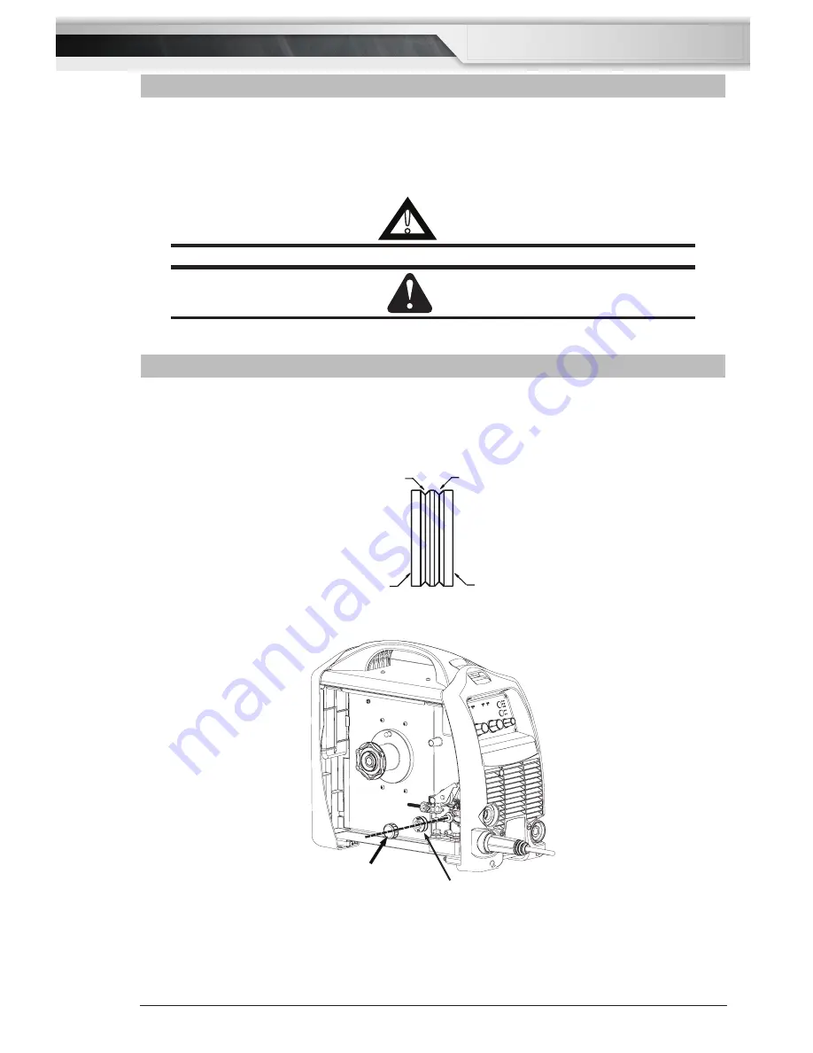
5.07 Changing the Feed Roll
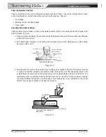
To change feed roll remove the feed roll retaining screw by turning in an anticlockwise direction. Once the feed
roll is removed then to replace feed roll simply reverse these directions.
A dual groove feed roller is supplied as standard. It can accommodate 0.6/0.8mm diameter hard wires. Select
the roller required with the chosen wire size marking facing outward.
GROOVE “B”
GROOVE “A”
GROOVE “A” SIZE
GROOVE “B” SIZE
A-09583
Figure 5-8: Dual Groove Feed Roller
Feed Roll
Retaining Screw
Feed Roll
Art #
A-12908
Figure 5-9: Changing the Feed Roll
Summary of Contents for Transmig 165ST
Page 16: ...SERVICE MANUAL Transmig 165ST Transmig 165ST GENERAL INFORMATION 1 10 Manual 0 5442 Notes ...
Page 32: ...OPERATION 4 6 Manual 0 5442 SERVICE MANUAL Transmig 165ST Transmig 165ST Notes ...
Page 84: ...SERVICE MANUAL Transmig 165ST Transmig 165ST THEORY OF OPERATION 9 2 Manual 0 5442 Notes ...
Page 120: ...SERVICE MANUAL Transmig 165ST Transmig 165ST ASSEMBLY PROCEDURE 12 8 Manual 0 5442 Notes ...
Page 125: ...SERVICE MANUAL Transmig 165ST Transmig 165ST This Page Intentionally Blank ...

