13
MAINTENANCE
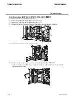
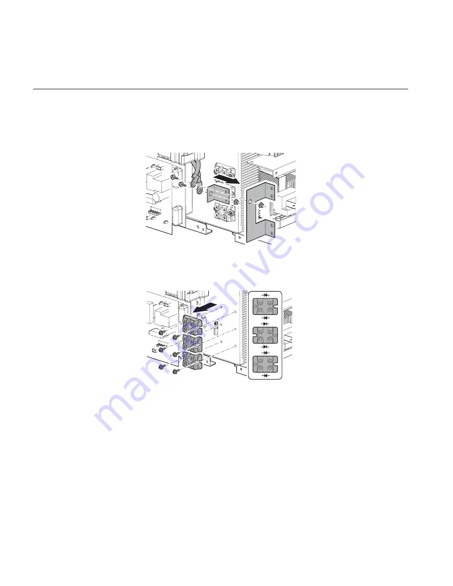
3.31 Secondary Diode (D2, D4, D5)
UV\
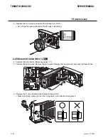
1 ) Remove the Side Panel. [Reference page: 11-1]
2 ) Remove the PCB13 (WK-5569). [Reference page: 12-18]
3 ) Remove the PCB12 (WK-5615). [Reference page: 12-15]
4 ) Remove the two screws and two nuts and remove the bus bar.
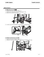
5 ) Remove the six screws and then detach the Secondary Diode (D2, D4, D5).
Do not have the wrong direction of the diodes when reinstalling.
Before installing a new diode, apply a uniform coat of silicone compound (Shinetsu Silicone G-747
or equivalent) on the base.
January 17, 2008
13-33
SERVICE MANUAL
TRANSTIG 200 AC/DC
January 17, 2008
13-33
Summary of Contents for TRANSTIG 200 AC/DC
Page 8: ...THIS PAGE LEFT INTENTIONALLY BLANK ...
Page 20: ...TRANSTIG 200 AC DC SERVICE MANUAL 2 6 January 17 2008 NOTES ...
Page 34: ...5 2 January 17 2008 TRANSTIG 200 AC DC SERVICE MANUAL NOTES ...
Page 58: ...January 17 2008 11 2 TRANSTIG 200 AC DC SERVICE MANUAL NOTES ...
Page 74: ...TRANSTIG 200 AC DC SERVICE MANUAL January 17 2008 12 16 THIS PAGE LEFT INTENTIONALLY BLANK ...
Page 111: ...THIS PAGE LEFT INTENTIONALLY BLANK SERVICE MANUAL TRANSTIG 200 AC DC January 17 2008 13 37 ...
Page 122: ...A 11 January 17 2008 TRANSTIG 200 AC DC SERVICE MANUAL NOTES ...
Page 126: ......


