January 17, 2008
4-1
SERVICE MANUAL
TRANSTIG 200 AC/DC
SECTION 4:
OPERATOR CONTROLS
4.01 Transtig 200 AC/DC Controls
1
3
2
5
4
8
6
7
A
r
t # A-08341_AC
Figure 4-1: Transtig 200 AC/DC Power Source
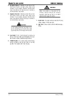
1. Control Knob:
This control sets the selected weld
parameter, rotating it clockwise increases the
parameter that is indicated on the digital meter.
Pushing the knob inward displays the actual welding
voltage.
2 . Remote Control Socket:
The 8 pin Remote
Control Socket is used to connect remote current
control devices to the welding Power Source. To
make connections, align keyway, insert plug, and
rotate threaded collar fully clockwise.
A
r
t # A-04984
2
1
5
4
3
6
7
8
1 2 3 4 5 6 7 8
5k Ohms
GND
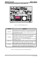
Figure 4-2: 8-Socket Receptacle
Socket Pin
Function
1
Earth (Ground)
Torch Switch Input (24V) to
(connect pins 2 & 3 to turn on
welding current)
3
Torch Switch Input (0V) to
energize weld current (connect
pins 2 & 3 to turn on welding
current)
4
Not Used
5
5k ohm (maximum) connection
to
5k
ohm
remote
control
potentiometer
6
Zero ohm (minimum) connection
to 5k ohm remote control
potentiometer
7
Wiper arm connection to 5k ohm
remote control potentiometer
8
Not Used
2
Table 4-1: Socket Pin Functions
Summary of Contents for TRANSTIG 200 AC/DC
Page 8: ...THIS PAGE LEFT INTENTIONALLY BLANK ...
Page 20: ...TRANSTIG 200 AC DC SERVICE MANUAL 2 6 January 17 2008 NOTES ...
Page 34: ...5 2 January 17 2008 TRANSTIG 200 AC DC SERVICE MANUAL NOTES ...
Page 58: ...January 17 2008 11 2 TRANSTIG 200 AC DC SERVICE MANUAL NOTES ...
Page 74: ...TRANSTIG 200 AC DC SERVICE MANUAL January 17 2008 12 16 THIS PAGE LEFT INTENTIONALLY BLANK ...
Page 111: ...THIS PAGE LEFT INTENTIONALLY BLANK SERVICE MANUAL TRANSTIG 200 AC DC January 17 2008 13 37 ...
Page 122: ...A 11 January 17 2008 TRANSTIG 200 AC DC SERVICE MANUAL NOTES ...
Page 126: ......

