GB
GB
GB
GB
GB
5
5
5
5
5
Installation
Installation
Installation
Installation
Installation
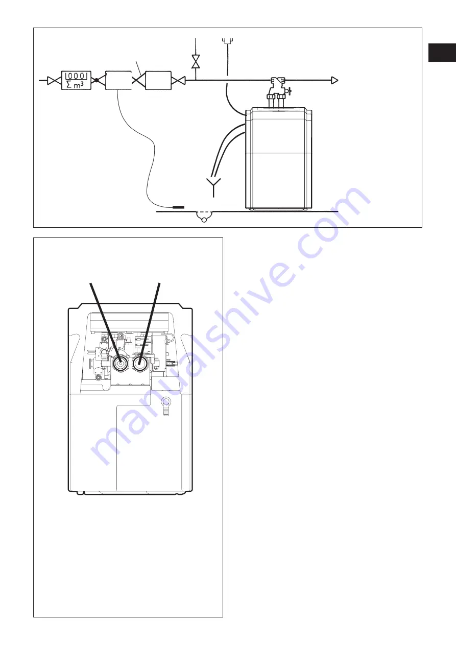
Connect the unit according to the adjacent diagram.
Connect the corrugated hose outlet
outlet
outlet
outlet
outlet with the hard
hard
hard
hard
hard
w
w
w
w
water inlet
ater inlet
ater inlet
ater inlet
ater inlet and the corrugated hose inlet
inlet
inlet
inlet
inlet with the
softened w
softened w
softened w
softened w
softened water outlet
ater outlet
ater outlet
ater outlet
ater outlet.
Be sure to obser
Be sure to obser
Be sure to obser
Be sure to obser
Be sure to observ
v
v
v
ve the arro
e the arro
e the arro
e the arro
e the arrows indicating the
ws indicating the
ws indicating the
ws indicating the
ws indicating the
direction of flo
direction of flo
direction of flo
direction of flo
direction of flow
w
w
w
w.
Installation Diagram
Installation Diagram
Installation Diagram
Installation Diagram
Installation Diagram
Hydro-
stop
Filter
Pressure reducer
Floor drain
Hardwater-
Hardwater-
Hardwater-
Hardwater-
Hardwater-
inlet
inlet
inlet
inlet
inlet
Softwater-
Softwater-
Softwater-
Softwater-
Softwater-
outlet
outlet
outlet
outlet
outlet


