-
14
-
Metal Dog Tag 500 / Metal Dog Tag 500 Plus
Manuale Operatore
rev 04-2008
Operator Manual
PANNELLO POSTERIORE
REAR PANEL
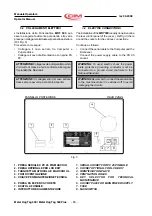
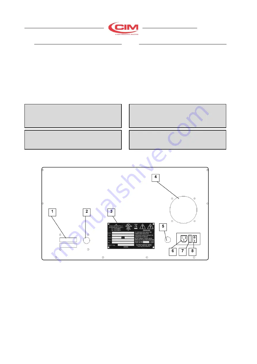
Fig. 3
3.2 COLLEGAMENTI ELETTRICI
L’installazione della Punzonatrice
MDT 500
può
essere eseguita facilmente accedendo alle varie
prese per i collegamenti situate sul pannello posteriore
(Rif. Fig. 3).
Procedere come segue:
•
Collegare il cavo seriale tra Computer e
Punzonatrice
•
Collegare il cavo di alimentazione con spina PA
80
ATTENZIONE:
Collegare solo ad impianti provvisti
di circuito di messa a terra conforme alle regole
Impiantistiche Nazionali.
ATTENZIONE:
Il collegamento del cavo seriale
deve sempre avvenire a macchina spenta.
1. PRESA SERIALE X PC 25 PIN MASCHIO
2. PRESA OPZIONALE PER LCD EDIT
3. TARGHETTA MATRICOLA E MARCHIO UL
4. FORI DI VENTILAZIONE
5. CHIAVE PER MANUTENZIONE TECNICA
6. PRESA PA 80 PER CAVO RETE
7. SCATOLA FUSIBILE
8. INTERUTTORE DI ALIMENTAZIONE
3.2
ELECTRIC CONNECTIONS
The installation of the
MDT 500
is easily done. Examine
the rear control panel of the cover, ( Ref fig 3 ) there
are all the sockets for the various connections.
Continue as follows:
•
Connect the serial cable to the Computer and the
Embosser
•
Connect the power supply cable to the PA 80
socket.
WARNING:
To avoid electric shock the power
plate protective grounding conductor must be
connected to a ground circuit conforms to the
National Standard.
WARNING:
Remember to connect the serial cable
to the machine while it is switched off to avoid
damaging the circuits.
1. SERIAL SOCKET FOR PC 25 PIN MALE
2. SOCKET OPTIONAL FOR LCD EDIT
3. IDENTIFICATION PLATE
4. VENTILATION HOLES
5. KEY SELECTOR FOR TECHNICAL
MAINTENANCE
6. SOCKET PA80 FOR MAIN POWER SUPPLY
7. FUSE
8. MAIN SWITCH


