Plus 42 - 45 - 50 - 55
09-2008
16
P4
P6
P12
BS
BP
P7
T6
T1
T2
T9
TR
T4
E9
P1
P13
d
b
a
c
P14
m.
AUTO
P
RO
ON
OFF
1
2
3
1
2
3
Pro
D
MAN
2xP
OFF
ON
3
2
1
1
2
3
G
1 2 3 4 5 6 7 8 9 10 11 12
Ha
Km/H
Bar
L/Ha
2.0
250
3.0
12.58
E8
P8*
E5
P11
T5
b
c
a
P2
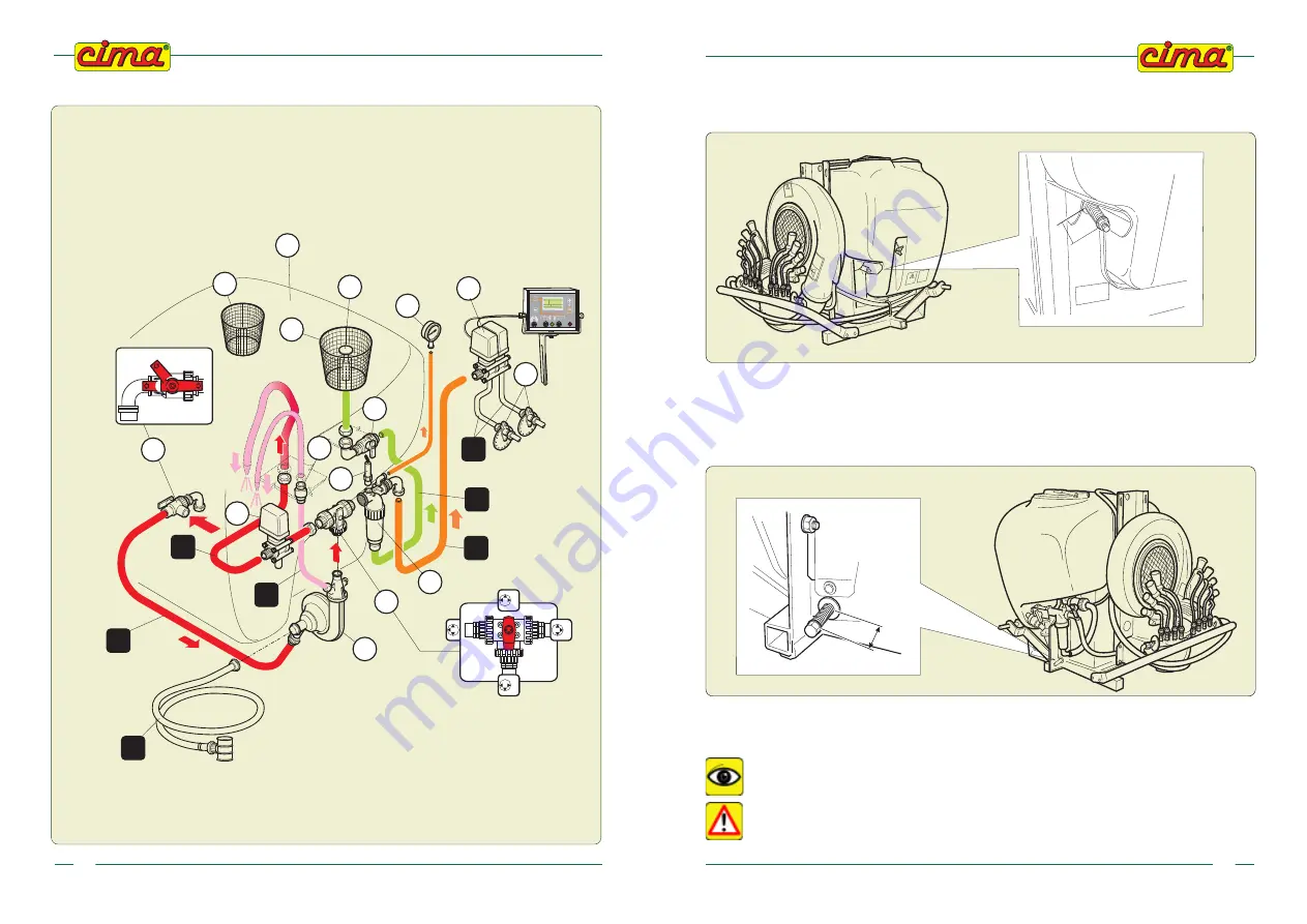
E.P.A. Versions
LEGEND:
P - E = elements of the circuit
T = piping
Hydraulic connections diagram
TANK
SUCTION
PIPE
FILLER PIPE
(ACCESSORY)
TO THE
DISTRIBUTION
HEAD
DUST
PRODUCTS
MIXER
00964
FILTER
AGITATION
PIPE
HYDRAULIC
AGITATION
MIXER
PIPE
DELIVERY
PIPE
PUMP
RETURN TO TANK
PIPE
09-2008
Plus 42 - 45 - 50 - 55
53
The belt setting will take place within the first 2 operating hours; when that time has elapsed, verify
the spring length, according with the time intervals (periodicity) indicated in the “Maintenance
operations’ table”.
13.8 - PUMP BELT TENSIONER
Check length “L” of the spring (refer to picture): it should be in tension between
4 and 5
cm.
If the value measured exceeds 5 cm, tighten the belt tightener screw, up to get the minimum length (4
cm).
00098
L
L = 9 ÷ 12 cm
00128
L
L = 4 ÷ 5 cm
00099
00298
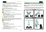
13.9 - TANK REMOVAL OR REPLACEMENT
It is recommended to have the operation performed by a C.I.M.A. assistance point, such a
regulation is compulsory in case of REPLACEMENT of the tank.
The operation has to be carried out by complete absence of liquid residuals both
inside the tank and in the hydraulic circuit.


