Plus 42 - 45 - 50 - 55
09-2008
18
P1. TANK
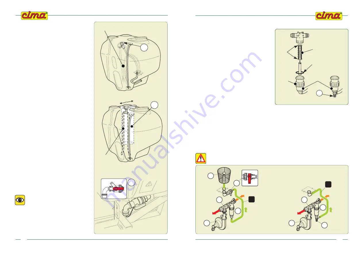
Tanks utilised:
polyethylene tanks of 300, 400 and 600 litre
capacity.
Each tank is made up of:
— tank main filler spout of 355 mm diameter, with
collapsible lid, breather and labyrinth seal, for
the filling with spraying products. Plastic cup-
like filter: 302 mm external diameter, height
254 mm with powder mixing device (for
versions in which this envisaged);
— supplementary tank filler with 250 mm diam-
eter screw-type lid, for filling with clear
water and plastic cup-like filter: external
diameter 204 mm, height 240 mm;
— transparent level indicator external pipe with
graduated scale;
— hydraulic agitation system connected to the
regulator (P5) and to the pump (P4).
— pneumatic agitation, connected to the piston
tap found above the tank and connected
through piping to the air intake located on the
fan casing.
A = OPEN
C = CLOSED
HYDRAULIC
AGITATION
“A”
“C”
HAND WASHING
TANK
PNEUMATIC
AGITATION
00075
00188
P2 - 3-WAY LEVER TAP A WITH
DISCHARGE FITTING
Fixed to tank (P1) and connected to the suction
piping (T1).
With the machine in operation the
tap’s lever must face towards the
suction piping (position “a”).
By positioning the lever towards
the drain plug (position “c”), total
draining of the tank is obtained.
In order to carry out the complete
discharge of any liquid remaining in
the pump and pipes, set the tap to
position “b”.
b
c
a
P2
00019
P22. HAND WASHING TANK
Incorporated polyethylene 17 litre capacity hand
wash tank, with external service tap; opening
though a 255 mm diameter screw lid.
P22
P5
09-2008
Plus 42 - 45 - 50 - 55
51
13.4 - CLEANING OF FILTER’S CARTRIDGE
7.
Reassemble the cartridge and secure the lid with the thumb screw.
Pay attention to the O-Ring
of the lower body during the assembly
: the incorrect sealing of the filter will jeopardise the
proper operation of the sprayer and cause loss of the mixture.
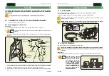
13.5 - PURGING OF RESIDUES FROM FILTER
With the machine in operation and the taps of the manual (P9) or electrical (E9) distributor closed.
Opening the powder mixer tap (P12) (or the self-cleaning filter faucet P25 -
for versions where it is
foreseen) the delivery flow will drag possible sludge to the bottom of the filter within the tank through
the piping (T6) thus partially cleaning the filtering cartridge. Close the tap when the operation is
completed.
When the machine is in operation, check that the drain tap (P12) (or P25) is closed
before opening the main feeder.
00306
FILTERING
CARTRIDGE
O.RING
O.RING
LOWER
BODY
OF FILTER
KNOB
1.
Set the lever of 3-way tap (P6) to the “d”
position
2
.
Completely close the pressure regulator, by
turning clockwise the handle of the manual
regulator (P5) or by turning the pressure up
(keep the joystick on “+” for about 15 secon-
ds) if the atomizer is provided with electric
regulator (E5).
3. Verify that the faucet (P12) of the powders
mixer (or the faucet of the self-cleaning filter
P25 - for the versions provided with) is
closed.
4.
Close the manual distributor’s taps (P9) or
position the switches of the control electric
switchboard (E10) on “OFF”
5. Undo the thumb screw and remove the body
of the filter.
6. Extract the cartridge: clean the grill and the
retaining O.Ring.
P25 *
* for versions where it is foreseen
P6
P4
P7
T6
P13
a
c
P12
P6
P4
P7
T6
P25
*
*
*
* for versions where it is foreseen
00975


