Plus 42 - 45 - 50 - 55
09-2008
24
E10. CONTROL UNIT
(for versions provided with)
It is electrically connected to the distributor with
2 motorised solenoid valves (E9) and to the main
socket of the tractor (Lighter tap).
The 2 lever switches, controlling the solenoid
valves (E9), have to be set to “ON” for opening
and to “OFF” for closing. The control unit is
equipped with a bayonet support to be inserted
in the bracket provided. This must be mounted on
the tractor, within the driver’s reach. When the
machine isn’t hitched to the tractor, it must be
®
ON
Remote Control
H O
2
ON
OFF
OFF
00971
1
2
2
3
LEGEND
1 - UNION FLANGES
2 - LOCKING NUT
3 - ROTATING DISC WITH CALIBRATED HOLES
00026
Any faulty sealing condition of the
hydraulic circuit causes an intermit-
tent issuing of the sprayed mate-
rial. It is necessary to carefully che-
ck the efficiency of the sealers and
clamps, the tightening of the ring
nuts and fittings and the good
working condition of the piping.
P17. SPRAY-LINE RINSING TANK
placed in the position foreseen on the forward part of the machine frame.
P11. CALIBRATION DISC
(Patent N° 23238)
It selects the flow rates necessary to the treatment and is mounted on the distribution devices. It is
made up of 2 flanges, held in position by two butterfly nuts, locking a disc with calibrated holes numbered
from 1 to 15. A groove on the edge of the disc allows the exact positioning of the hole to be utilised.
Its number must appear in the flange’s semi-circular seat. The rotation of the disc is obtained by
loosening the butterfly nuts by a few turns. After the operation is done, screw back carefully.
SPRAY-LINE
RINSING
TANK
(for versions provided with)
The tank, 45 liters capacity, is made of polyethy-
lene and is supplied with a filler and pipelines
connecting to the machine hydraulic circuit.
09-2008
Plus 42 - 45 - 50 - 55
45
P15
b
a
c
d
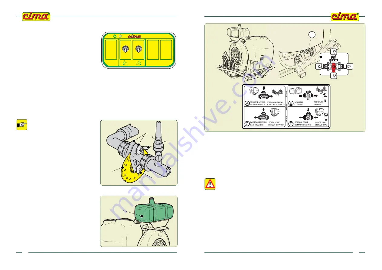
10.5 - END OF TREATMENT - STORAGE
10.5.1 - Daily
•
The operator must:
a
. Wash the machine’s exterior before cleaning out the hydraulic circuit. The operative sequence will
permit the elimination of possible water residues from the fan casing and piping conveying the air
flow to the heads.
The washing of the sprayer’s exterior must be carried out in an area in which foul
waters are collected in a disposal pit. DO NOT UTILISE HIGH-PRESSURE HYDRO-
CLEANERS.
b
. Carry out the complete hydraulic circuit cleaning process, by washing the tank inside with a clean
water jet; then, he has to operate the sprayer, by spraying the tank contents on the ground, in
conformity with the antipollution directives in force in the country where the machine is employed:
if necessary, repeat the whole procedure.
c
. Check the efficiency of the distribution device (head) and the cleaning of the pulverising points
(diffusers), possibly replacing them if found to be damaged.
d.
Clean out the filter cartridge.
e
. Keep the machine in a ventilated place, sheltered from rain or sun: sunrays are the worst enemies
of plastic and rubber parts.
00682
00676


