background image

27 


Compressor air intake 

Column Mounting  Bolts 

Foot Pad 

Engine Access Panel 

Engine Oil Dipstick Access 

Fuel Tank Filler Neck 

Engine cooling air intake 

Compressor oil sight glass 

Compressor Oil Fill Port 

Ignition Key 

System Pressure Gauge 

Choke 

Hour Meter 

Identifying Components Continued


Bullet 2, Controls Side 

Tie Down Point 

Column 

Tie Down Point 

Compressor 

Lifting  tube 

Compressor Access Door 

Summary of Contents for 301-000-000

Page 1: ...Stand Alone Compressor with Boom Arm Owner Operators Manual 2601 Niagara Lane Plymouth MN 55447 763 557 1982 800 328 3874 Fax 763 557 1971 Part 301 000 000 6 22 2021 ...

Page 2: ...machine can expose you to dust containing crystalline silica and engine exhaust which contains chemicals that are known to the State of California to cause cancer birth defects or other reproductive harm For more information go to www P65Warnings ca gov ...

Page 3: ...ng the Boom Column 12 Initial Start Up 13 Lifting the X2 14 Securing the X2 15 Operating the X2 16 18 Start Up 16 17 During Operation 18 Shutting Down 18 General Maintenance 19 23 Fuel 19 Cleaning 19 Engine service 20 Compressor service 20 Maintenance schedule 20 21 Storage Preparation 22 Removal from storage 23 Trouble Shooting 24 25 Component Identification 26 31 Service Part List 32 33 Notes 34...

Page 4: ...Serial Number Model Number X2 Compressor Model Bullet G Compressor Manufacturer Boss Compressor Serial Number Engine Model H P CH730 Engine Manufacturer Kohler Engine Serial Number Read Instruction Manual Reading the instructions completely is the first step to safe operation An uninformed operator can subject himself and others to death or serious injury This manual contains the basic information...

Page 5: ...D BEFORE OPERATING EQUIPTMENT You are in a position to ensure the safety of yourself and those around you Lack of attention to safety can result in accidents personal injury reduction in efficiency and worst of all loss of life Watch for safety hazards and correct them promptly Understanding the proper operation of this equipment is critical to its safe operation In addition to following these saf...

Page 6: ...ng in close proximity to the air nozzle must always wear personal protective equipment PPE The PPE must be well maintained and in proper working order Required PPE includes Gloves with wristlets Heavy leather boots or shoes Face Shield Long sleeve shirt with sleeves rolled down and cuffs buttoned Long pants with no cuffs Respirator Hearing Protection ...

Page 7: ... when working in close proximity to this equipment CAUTION FLYING DEBRIS HAZARD Airborne debris may cause eye injuries ALWAYS wear eye protection such as a face shield or safety glasses to avoid injury from flying debris CAUTION COMPRESSED AIR NEVER direct a stream of compressed air towards your body or the body of another person as this may cause serious injury or death DO NOT use compressed air ...

Page 8: ... from the inside and around the compressor Carefully clean up any gas or oil spills before starting the unit DO NOT use flammable solvents to clean the compressor FIRE AND BURN HAZARD Gasoline is an extremely flammable liquid and vapor Negligence or improper care can cause fire NEVER fuel a running or hot engine Ensure there are no fuel leaks before starting engine Keep sources of sparks and flame...

Page 9: ...ine exhaust as it is extremely hot leaving the muffler CAUTION PRESSURIZED SYSTEM Sudden rapid and uncontrolled decompression of the system can lead to death or serious injury DO NOT attempt to remove any part of the compressor without completely relieving the entire system of pressure DO NOT attempt to service any part of the equipment while in operation NEVER attempt to repair or modify any pres...

Page 10: ...From Bed 40 to 55 Cab Clearance 68 58 125 44 Weight and Dimensions Weight without hose and wand 975 lbs Fuel tank capacity 5 gallons Compressor oil capacity 2 gallons Compressor output 70 cfm 100 psi 58 Folded Boom ...

Page 11: ...tand or climb on any part of the machine DO NOT operate compressor without access panels DO NOT block or restrict airflow into and out of the compressor Reference the Boss Bullet G manual for further details STAY CLEAR from engine exhaust along with heated air from the radiator and engine Remove large debris and other potential projectiles from the work area STAY BACK from the work area of the air...

Page 12: ...ocate and mark the new holes To get the adjustment distance subtract 40 from the required clearance Measure upward from the bolts holding the column in place Select the holes just past the measurement to give you extra clearance Example If the measured clearance height is 49 75 after subtracting 40 you end up with 9 75 You would select the holes at the 12 mark not the 9 mark 3 Remove the 4 bolts h...

Page 13: ... 3 Check the oil level of the engine 4 Confirm the oil level of the compressor 5 Confirm all the mechanicals are in working order 6 Replace any panels that may have been removed during inspection and set up 7 Open the air valve and relieve any pressure Close the valve only after all pressure has been relived 8 Fill the fuel tank start the engine allow 3 5 minutes to warm up and then open the valve...

Page 14: ...center of gravity makes hoisting the X2 difficult and dangerous serious injury or death may occur ONLY people trained in making such complex lifts with the proper equipment may attempt hoisting the unit 2 Place the unit onto the bed of the truck in between the wheel wells and against the cab end of the bed If a flatbed is being used the unit should be loaded from the rear moved to the front of the...

Page 15: ...the straps and tip 2 The straps at the cab end of the bed are to be strung to the tie down loops at the top of the column 4 After all straps are strung begin tightening starting with the rear passenger corner Followed by the rear drivers front passengers and the front drivers Lastly go back through and confirm all are tight Permanent Mounting Options The X2 is supplied with foot pads that allow fo...

Page 16: ...y opening the air valve and any valve down stream WARNING NEVER perform any maintenance on the compressor unit without first releasing any all stored pressure Failure to comply can lead to equipment damage severe injury or even death 3 Check fuel level engine oil compressor oil level inspect both air cleaners all air hoses and fittings for damage 4 Attach the air hose and blowout tool to the boom ...

Page 17: ...during startup will force the engine to run at higher than recommended speeds before it has properly warmed up 9 Start the engine by activating the key switch using the choke as needed Release the switch as soon as the engine starts NOTICE Do not crank the engine continuously for more than 10 seconds at a time If the engine does not start allow a 60 second cool down period between starting attempt...

Page 18: ...NG The compressor will be extremely hot from operation Use care when shutting it down and working around it to avoid severe burns Personal Protective Equipment PPE such as heat proof gloves are recommended 1 With the vehicle parked and emergency break engaged close the air valve on the compressor 2 Allow the compressor to run an additional 3 to 5 minutes to cool down before turn ing key to off 3 C...

Page 19: ...emove dirt and debris from the compressor unit CAUTION NEVER use flammable solvents to clean the engine or compressor CAUTION DO NOT use a vacuum to clean the compressor The debris around the engine and compressor may contain flammable compounds from spilled oil or gasoline that can ignite CAUTION DO NOT clean the interior of the compressor while it is hot Allow it to cool before cleaning to avoid...

Page 20: ...e Boss Product Manual for the Bullet G and follow the maintenance instructions If service or repair of compressor is needed contact Boss Industries Service Center at 800 635 6587 or email at service bossair com Daily Maintenance Check engine oil Add oil if low Check compressor oil level adding or draining fluid as necessary NOTICE To maintain warranty coverage use only Boss Industries Shield Works...

Page 21: ...d clean cooling areas Check oil cooler fins clean as necessary Grease the boom pivot joint Every 200 hours Change engine oil filter Replace fuel filter Every 250 hours Replace engine air cleaner paper element Every 500 hours or yearly Replace sparkplugs and set their gap Have crankshaft spline lubricated Clean battery terminals Check battery hold down and cables for wear Check compressor air filte...

Page 22: ... Run the compressor for 20 to 30 minutes to help remove water from the compressor oil 2 Drain the fuel tank and lines add fuel stabilizer to any remaining fuel 3 Run the engine until it stalls to empty all fuel out of the carburetor 4 Consult the Kohler Command Pro Owner s Manual or a Kohler service technician for proper storage preparation of the engine 5 Disconnect the Negative battery cable 6 R...

Page 23: ...ters engine area as well as the exhaust 3 If fuel was drained out of the tank fill the unit with FRESH gas Old un stabilized gasoline can cause hard starting and may damage the engine 4 Move the unit outdoors and away from vents 5 Start the engine and let it run until it is warm and test the compressors air flow NOTICE If your engine cylinders were fogged or oil coated prior to storage the smoky e...

Page 24: ... open to atmosphere Leaks in service line fittings Restricted compressor air inlet filter Faulty regulator Faulty inlet valve Low engine speed Belt slip High Discharge Pressure Oil separator plugged blocked Safety valve inoperative Faulty regulator Faulty inlet valve Coalescer Plugging Compressor oil breaking down Excessive water in oil sump Foreign material entering compressor inlet Compressor Oi...

Page 25: ...ing Continued For issues generally related to the compressor refer to the Boss Bullet G manuals Maintenance and Trouble shooting section For Issues directly related to the engine refer to the Kohler Command Pro manual ...

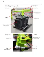
Page 26: ...view Grease Zerk Plastic Chanel Guide P N 301 057 000 Pivot Pin Latch Pin Latch Body Bullet 2 Compressor P N 301 058 004 Boom Boom Column Manual Boom Release Boom Rest and Pin P N 101002 Boom Latch Boom Latch Swivel P N 301 060 601 ...

Page 27: ...Access Fuel Tank Filler Neck Engine cooling air intake Compressor oil sight glass Compressor Oil Fill Port Ignition Key System Pressure Gauge Choke Hour Meter Identifying Components Continued Bullet 2 Controls Side Tie Down Point Column Tie Down Point Compressor Lifting tube Compressor Access Door ...

Page 28: ...ne P N 301 061 601 Lifting tube Foot Pad Foot Pad Lifting tube Battery Access Panel Not Shown Engine Muffler Exhaust Tie Down Point Compressor Identifying Components Continued Bullet 2 Exhaust Side Bullet 2 Oil Cooler End ...

Page 29: ...Oil Filter Compressor Oil Cooler Compressor Oil Drain Plug Compressor Oil Sump Compressor Oil Filter Regulator DO NOT ADJUST Compressor Compressor Oil Sight Compressor Oil Filler Cap View shifted to show oil drain plug Identifying Components Continued Bullet 2 Compressor Access Door ...

Page 30: ...ator Drive Belt Starter Fuel Vapor Carbon Canister Battery Belt Tensioning Bolt Pressure Relief Valve Electric Fan Compressor Oil Cooler Fuel Tank Engine Oil Filter Engine Oil Drain Identifying Components Continued Bullet 2 Panels Removed Exhaust Side ...

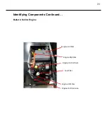
Page 31: ...31 Identifying Components Continued Bullet 2 Kohler Engine Engine Air Filter Engine Dip Stick Engine Oil Fill Point Fuel Filter Engine Oil Filter Engine Oil Drain Line ...

Page 32: ... H P CH730 Engine Manufacturer Kohler Engine Serial Number Cimline Part Description 110889 Oil Filter Kohler CH730 301 910 000 Fuel Filter Kohler CH730 301 911 000 Air Filter Pre Cleaner Kohler CH730 301 912 000 Air Filter Paper Element Kohler CH730 301 913 000 Kit Air Cleaners Kohler CH730 301 914 000 Kit Air Cover w Knob Kohler CH730 Engine Service Parts Engine Service Parts Service parts for th...

Page 33: ... Carbon Canister 301 906 000 Kit 50 Hour Service Boss Bullet 2 301 907 000 Kit 500 Hour 1 Year Service Boss Bullet 2 301 908 000 Cap Fuel Non Vented EPA w Tether 301 909 000 Cap Air Filter 2 Compressor System Service Parts For parts directly related to the compressor you may also contact Boss Industries Service Center at 800 635 6587 or email at service bossair com Please refer to the Boss Bullet ...

Page 34: ...34 Notes ...

Page 35: ...35 ...

Page 36: ...2601 Niagara Lane Plymouth MN 55447 763 557 1982 800 328 3874 Fax 763 557 1971 ...

Reviews: