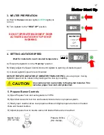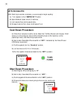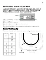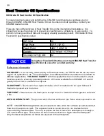
25
(A)
ME3
OIL LEVEL - OIL MUST BE AT, OR
JUST ABOVE, THE END OF THE
PROBE
Do not operate machine when heat transfer oil is below the
marking line or significant damage to machine can occur.
NOTICE
ME3 Maintenance - Changing Heat Transfer Oil
CHANGING/REPLACEMENT OF HEAT TRANSFER OIL:
1) Remove the dipstick
(A)
and fill cap
(B)
of the HTO tank
.
2) Drain from the bottom of the vessel (under the trailer)
through the 3/4” pipe cap
(E)
. Use two wrenches to re-
move the drain cap, you do not want the pipe to come
unscrewed, just the cap on the end of the pipe.
3) Replace the 3/4” drain plug
(E)
and refill with the correct
amount of heat transfer oil as stated on page 21 by pour-
ing through the tank fill cap
(B).
4) Replace the tank fill cap, and check for the proper heat
transfer oil level using the dipstick.
CHECKING HEAT TRANSFER OIL LEVEL:
NOTE:
Use dipstick (A) as provided for checking heat transfer oil
level when cold.
HEAT TRANSFER OIL LONGEVITY:
The regular interval for changing heat transfer oil is once annually or every 500 hours. If the time
frame between heat transfer oil changes is not known a significant difference in temperature from the
digital oil controller readout and the analog gauge may mean the oil has reached it’s service life and is
due to be changed. Oil that is not changed regularly can cause numerous problems including; slow
start-up times, incorrect controller temperature readings, oil crystalizing inside the vessel and damage
to the heat sensing probes.
Using oil that does not meet CIMLINE Heat Transfer Oil
specification is cause for a voided warranty.
NOTICE
Going under the trailer puts a person at risk of serious injury or
death. Follow procedure in the manual to stabilize trailer before
going under the trailer.
The melter operates at elevated temperatures which can cause
burns. Be sure the heat transfer oil is cool before performing
maintenance.
WARNING
(A)
(E)
(B)
DANGER
Summary of Contents for ME3
Page 15: ...15 Sub Control Panel Controls and Their Functions 1 2 3 4 6 7 8 5 ...
Page 34: ...34 Trailer Wiring Diagram ...
Page 39: ...39 Burner Internal Wiring Diagram ...
Page 43: ...43 Mastic Hydraulic Manifold Components ...
Page 44: ...44 Hydraulic Schematic ...
Page 49: ...49 Miscellaneous Parts 28 29 30 30 ...
Page 51: ......
Page 52: ...52 2601 Niagara Lane Plymouth MN 55447 763 557 1982 800 328 3874 Fax 763 557 1971 ...


