


37
ME3 Control Panel Wiring Diagram
NUMBER
COLOR
FUNCTION
AWG WIRE GAUGE
1
RED/BLACK STRIPE
BURNER POWER
14
2
RED/BLACK STRIPE
BATTERY (+)
12
3
WHITE
BURNER ENABLE
16
4
PINK
MICROPANEL ACCESSORY INPUT
16
5
GREEN/YELLOW STRIPE
BATTERY (-)
16
6
RED/BLACK STRIPE
ACCS. RELAY OUTPUT
16
8
RED/BLACK STRIPE
RELAY PANEL LUG TO VOLTMETER
16
9
GREEN/YELLOW STRIPE GROUND (ALL GROUND SYMBOLS ON DRAWINGS)
16
10
RED/BLACK STRIPE
RELAY PANEL LUG TO FUSE
16
11
ORANGE
FUSE TO PANEL SWITCH
16
12
ORANGE
PANE SWITCH TO CONTROLLERS
16
13
WHITE
MATERIAL CONTROLLER TO MATERIAL TEMP
16
14
RED/BLACK STRIPE
MATERIAL CONTROLLER TO MATERIAL TEMP
16
15
WHITE
OIL CONTROLLER TO OIL TEMP
16
16
RED/BLACK STRIPE
OIL CONTROLLER TO OIL TEMP
16
17
PURPLE
MATERIAL CONTROLLER TO LED
16
18
GRAY
OIL CONTROLLER TO MATERIAL CONTROLLER
16
19
PINK
MATERIAL CONTROLLER TO BURNER RELAY
16
20
GRAY
OIL CONTROLLER TO LED
16
21
PURPLE
FUSE TO BURNER RELAY
16
22
WHITE
BURNER RELAY TO LED
16
23
WHITE
TO BURNER STROBE
16
24
ORANGE
PANEL SWITCH TO LED
16
25
WHITE
PANEL SWITCH TO AGITATOR STOP
16
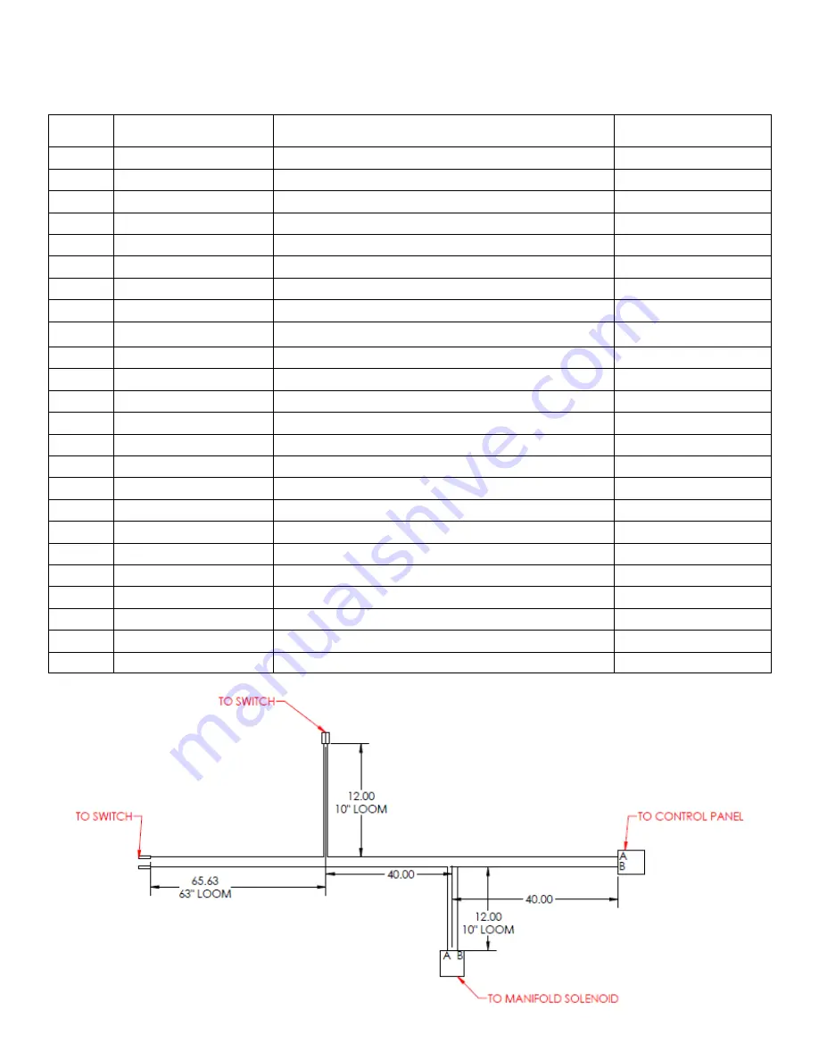
AGITATOR STOP HARNESS
Part # 308-275-000
Summary of Contents for ME3
Page 15: ...15 Sub Control Panel Controls and Their Functions 1 2 3 4 6 7 8 5 ...
Page 34: ...34 Trailer Wiring Diagram ...
Page 39: ...39 Burner Internal Wiring Diagram ...
Page 43: ...43 Mastic Hydraulic Manifold Components ...
Page 44: ...44 Hydraulic Schematic ...
Page 49: ...49 Miscellaneous Parts 28 29 30 30 ...
Page 51: ......
Page 52: ...52 2601 Niagara Lane Plymouth MN 55447 763 557 1982 800 328 3874 Fax 763 557 1971 ...


