


7
Wheels
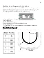
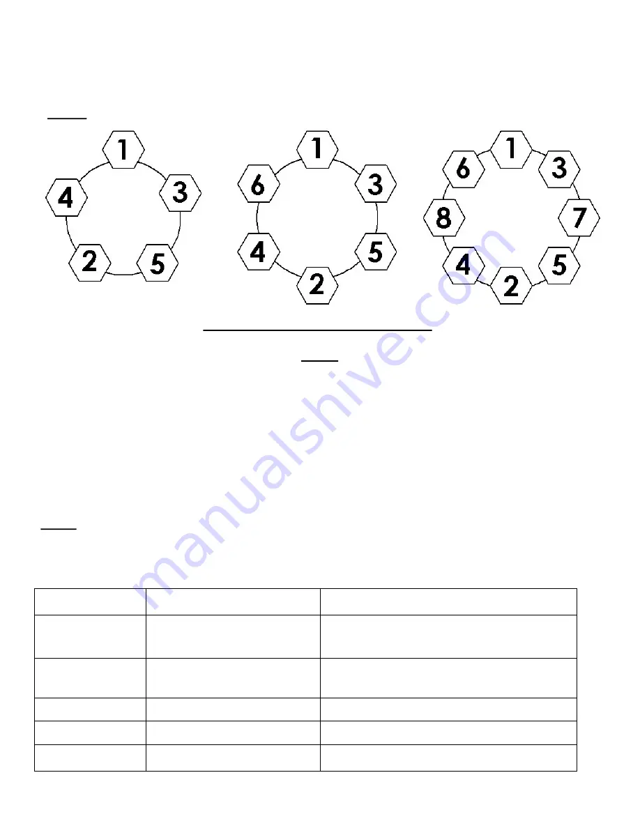
LUG TIGHTENING SEQUENCE CHART
TIRES
Prior to mounting tires onto wheels, be sure the rim size and contour are approved by the Tire and Rim
Association Yearbook or the Tire Manufacturers Catalog in the United States and Recreational Vehicle
Running Gear Certification - CSA CAN3 in Canada. Use only Tires, Rims and Wheels complying with
CMVTSS 109 and CVMTSS110; or CMBTSS 119 and CMVTSS 120. In addition, confirm that the tire will
carry the rated load. If the load is not evenly distributed on all tires, use the tire rated for the heaviest wheel
position. The Rubber Manufacturers Association or the tire manufacturers guidelines should be consulted for
mounting procedures. Tire inflation pressure is the most important factor in tire life. Tire pressure should
always be what is recommended by the manufacturer for the load. Always check pressure cold before
operation.
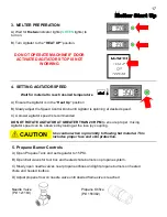
DO NOT
bleed air from tires when they are hot. Check inflation pressure weekly during use to
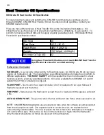
insure maximum tire and tread life. The following tire wear diagnostic chart will help you pinpoint the causes
and solutions of tire wear problems.
NOTE:
Tire wear should be checked frequently because once a wear pattern becomes firmly
established in a tire it is difficult to stop, even if the underlying cause is corrected.
Wheel Sizes
14” - 15” - 16” - 16.5” x 6.75”
NOTE:
All torque in ft-lb
Torque Sequence
1st Stage
2nd Stage
3rd Stage
20-25
50-80
90-120
PROBABLE CAUSE
CORRECTIVE ACTION
CENTER WEAR Over-inflation
Adjust pressure to particular load per tire catalog.
EDGE WEAR
Under-inflation
Adjust pressure to particular load per tire catalog.
SIDE WEAR
Loss of camber or overloading
Make sure load doesn't exceed axle rating. Align
at alignment shop or service center.
TOE WEAR
Incorrect toe-in
Align at alignment shop or service center.
CUPPING
Out-of-balance
Checking bearing adjustment and balance tires.
FLAT SPOTS
Wheel lockup & tire skidding
Avoid sudden stops if possible and adjust brakes.
Summary of Contents for ME3
Page 15: ...15 Sub Control Panel Controls and Their Functions 1 2 3 4 6 7 8 5 ...
Page 34: ...34 Trailer Wiring Diagram ...
Page 39: ...39 Burner Internal Wiring Diagram ...
Page 43: ...43 Mastic Hydraulic Manifold Components ...
Page 44: ...44 Hydraulic Schematic ...
Page 49: ...49 Miscellaneous Parts 28 29 30 30 ...
Page 51: ......
Page 52: ...52 2601 Niagara Lane Plymouth MN 55447 763 557 1982 800 328 3874 Fax 763 557 1971 ...


