Current-source Analog Output Blocks
June 2002
GFK-0691D
4
Block Operation ________________________________
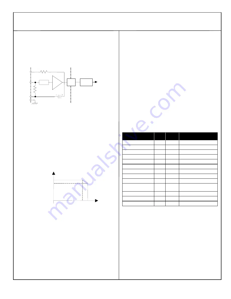
A Current-source Analog Input block has six independent inputs.
Input channels use voltage to frequency converters and counters to
translate analog currents to a digital value. This value is converted
by the block to engineering units before it is sent to the CPU. A
diagram of an input circuit is shown below.
EXC
24VDC
Processor
16 Bit
Counter
V to F
Opto
Isol.
100
COM
GND
Case
Ground
47
Filter
IN
Each input circuit has a 24 volt current loop power supply, capable
of providing 25mA of current. Each input is isolated from all other
circuits on the block. Input accuracy is 0.1%. Input conversion time
can be selected to provide the appropriate combination of noise
rejection and input resolution. Conversion times are programmable
from 16ms to 400ms. Resolution increases as the conversion time
is lengthened. Input resolution is 1µA for 200ms conversion time.
Upper and lower alarm limits can be programmed for each input
circuit. If either limit is exceeded, the block indicates a fault and
sends a message to the Hand-held Monitor and CPU.
The following illustration shows the input excitation current derating
versus temperature. The maximum excitation current per channel is
25mA.
30
60
90
120
0
10 20 30 40 50 60 70
150
temperature in degrees C
maximum excitation current
per block in milliAmps
Diagnostics _________________________________
The block’s advanced diagnostics provide the messages listed below.
Fault messages can be cleared from the Hand-held Monitor or the CPU.
Input Open Wire:
Input current is below 2mA.
Input High Alarm:
Input exceeds high alarm level.
Input Low Alarm:
Input exceeds low alarm level.
Input Overrange:
Signal exceeds 25mA.
Input Underrange:
Current is negative, or 0mA.
Configuration _________________________________
First, the block must be configured with a Hand-held Monitor to:
Enter its Device Number (serial bus address).
Enter its Reference Number (required only for IC600 and IC550
series PLCs only).
The rest of the features can be configured either using a Hand-held
Monitor, or by sending a Write Configuration datagram to the block from
the host.
Note:
If a block is configured offline, it must be properly grounded and
have a 75 Ohm resistor installed across its Serial 1 and Serial 2
terminals. See the
Discrete and Analog I/O Blocks User’s Manual
for
instructions.
Feature
Circuit
/Block
Factory
Setting
Selections
Device Number
Block
null
0 to 31 (must be selected)
Reference Address
Block
none
Depends on host CPU type
Baud Rate, Kbd
Block
153.6 std 153.6 std, 153.6 ext, 76.8, 38.4
Report Faults
Circuit
yes
yes/no
Channel active
Circuit
active
active/inactive
BSM Present
Block
no
yes/no
BSM Controller
Block
no
yes/no
CPU Redundancy
Block
none
none/standby
Input conversion time
Block
400ms
16 to 400ms
Input Scaling
Circuit
1µA per
eng unit
+/-32767 eng units
0 to +25000µA
Low Alarm
Circuit
0
+/-32767 eng. units
High Alarm
Circuit
+25000
+/-32767 eng. units
Configuration Protection
Block
disabled
enabled, disabled


