6
STEP 1: Blower / Motor Assembly.
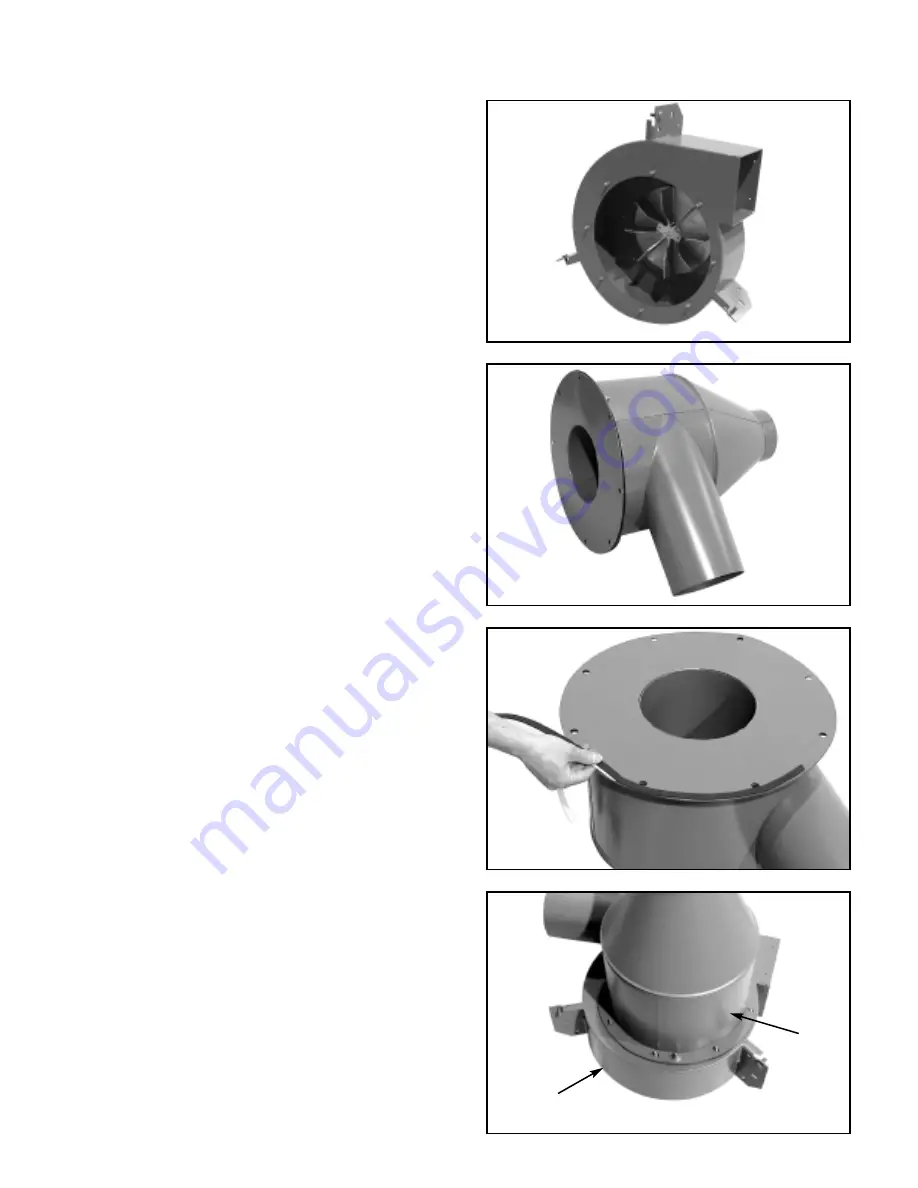
The blower/motor assembly
➁
is shipped as a pre-
assembled unit that includes the blower housing,
blower wheel, motor and the motor mounting plate.
Weight is over 250 pounds.
CAUTION:
This assembly is
very
heavy. Use a fork lift, hoist
or crane to remove this unit from the carton.
Lifting this unit by hand could cause a severe
back injury.
Set the assembly
➁
on the floor (on cardboard) in
position as shown in Fig. 2.
ASSEMBLY INSTRUCTIONS
NOTE: CUT PACKAGING CARDBOARD & PUT ON FLOOR TO PROTECT PAINTED PARTS DURING ASSEMBLY.
STEP 2: Cyclone Separator / Inlet Chip Deflector.
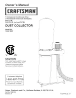
The cyclone separator and inlet chip deflector
➀
are
pre-assembled at the factory using two studs with
washers and nuts.
DO NOT unbolt these two parts.
Place this assembly on the floor (on cardboard) as
shown in Fig. 4.
STEP 3: Apply Gasket to Inlet Chip Deflector.
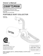
Remove a few inches of the paper backing from the
1
⁄
2
" wide x
1
⁄
8
" thick rubber gasket material. Start apply-
ing the gasket to the outer edge of the chip deflector
➀
as shown in Fig. 4 until a
complete circle
is
formed. Cut off any excess.
NOTE:
The purpose of
this gasket is to prevent air leakage into the blower.If
the gasket is not installed properly, sound levels will
also increase during operation.
STEP 4: Installing Cyclone/Chip Deflector assembly
➀
to the Blower/Motor assembly
➁
.
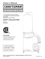
Gently
tilt blower up on top of motor per Fig. 5. There
are 8 threaded studs on the inlet side of the blower
assembly
➁
. Remove the protective sleeves from the
studs. Align the eight holes in the cyclone/chip deflec-
tor assembly
➀
with the threaded studs as shown in
Fig. 5.
NOTE: The inlet tube of the cyclone should
be pointing in the opposite direction to the blower
discharge.
Install (8) 3/8" flat washers, lock washers
and nuts onto the studs and tighten.
Gently
tilt hous-
ing back onto its side as in Fig. 2.
▲
Fig. 2
▲
Fig. 3
▲
Fig. 4
▲
Fig. 5
➀
➁


