9
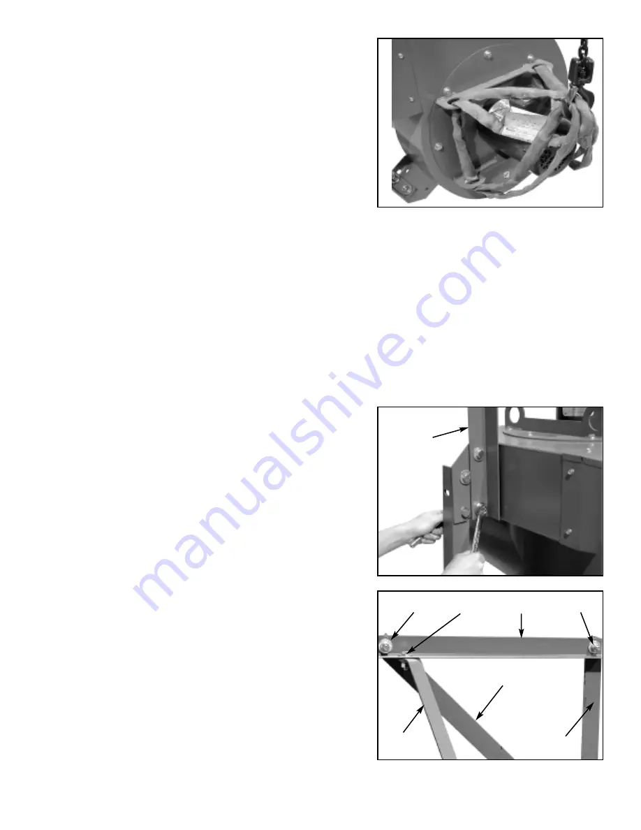
STEP 10: Lifting the dust collector.
a. Position the dust collector on the floor, with the two
legs nearest the motor resting on the floor.
CAUTION: the dust collector can be raised
mechanically or manually. Because of the weight
of the dust collector, we strongly recommend
using a forklift, hoist or crane with guide ropes to
set the unit upright.
b.
IMPORTANT:
Attach a sling or cable, with at least
a 750 pound live load capacity, to the lifting eyes
on the blower side plate as shown in Fig. 14. Using
guide ropes, carefully raise the dust collector to an
upright position on the floor.
c. Without removing the lifting sling or cable and
keeping the sling or cable taut, carefully check the
alignment of the blower housing and feet. The blow-
er housing should be level with the feet adjusted to
the floor surface.
d.
IMPORTANT: Carefully loosen all the mounting
hardware for the three legs from the blower
housing down to the feet, including the leg
cross braces. After you have leveled the unit
with the floor surface, completely tighten all the
hardware at each location.
STEP 11: Installing the Vertical Dust Bag Support.
The vertical bag support
➄
is 2" x 2" x
1
⁄
8
" angle iron,
47
1
⁄
4
" long with 4 holes. Install it to the blower housing
mounting lug at the bottom of the blower discharge.
Attach with two 1
1
⁄
4
" long bolts, four flat washers, two
lock washers and two nuts as shown in Fig. 15. Make
sure this section is vertical, then tighten the nuts.
STEP 12: Installing other Bag Supports & Braces.
a. The horizontal bag support
➅
is 2" x 2" x
1
⁄
8
" angle iron,
47
1
⁄
4
" long with 5 holes and mitered at one end. Bolt the
square end with one hole to the vertical bag support
➄
with a
1
⁄
2
" x 1
1
⁄
4
" bolt, two flat washers, one lock washer
and one one nut at location EE in Fig. 16.
b. Bolt the 2" x 2" x
1
⁄
8
" angle cross brace
➆
to the vertical
support
➄
, using the round hole at the mitered end.
Use the same size hardware as step “
a
” above.
c. Bolt the other end to the horizontal bag support
➅
, at
location FF, with a
1
⁄
2
" x 1
1
⁄
4
" long bolt, two flat washers,
one lock washer and a nut.
▲
Fig. 14
▲
Fig.15
▲
Fig.16
WARNING:
DO NOT assemble any casters to the
feet, as they will affect the stability of
the dust collector and create a hazard.
After the dust collector is in its final
position, the holes provided in the feet
should be used to anchor the dust col-
lector to the floor.
➈
➆
➄
➄
➅
FF
GG
EE


