CO
-
100/P1001
Series | User Manual
19
1.5.3 Left
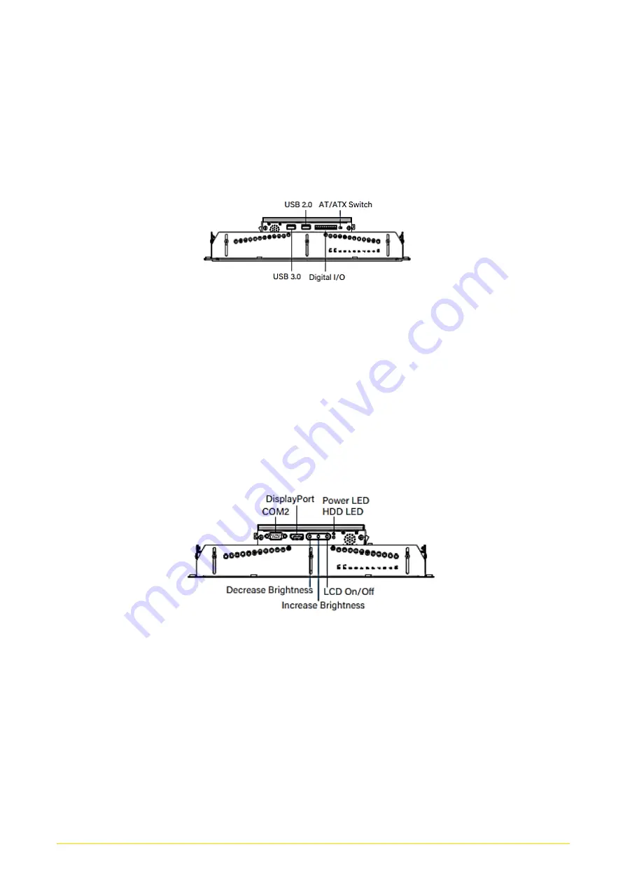
USB 3.0
Used to connect USB 3.0/2.0 device
USB 2.0
Used to connect USB 2.0 device
Digital I/O
The Digital I/O terminal block supports 4 digital
input and 4 digital output
AT/ATX Switch
Used to select AT or ATX power mode
1.5.4 Right
COM2
COM2 supports RS232/422/485 serial device
DisplayPort
Used to connect a DisplayPort devices
Power LED
Indicates the power status of the system
HDD LED
Indicates the status of the hard drive
OSD Function:
LCD On/Off
Press to turn-on or turn-off the display
Increase Brightness
Press to increase brightness of the screen
Decrease Brightness
Press to decrease brightness of the screen
Summary of Contents for CO-100/P1001 Series
Page 11: ...CO 100 P1001 Series User Manual 11 Chapter 1 Product Introductions ...
Page 17: ...CO 100 P1001 Series User Manual 17 Dimension CO W121C P1001 Unit mm CO W121C P1001E Unit mm ...
Page 20: ...CO 100 P1001 Series User Manual 20 Chapter 2 Jumpers Switches Connectors ...
Page 22: ...CO 100 P1001 Series User Manual 22 2 2 2 Bottom View ...
Page 31: ...CO 100 P1001 Series User Manual 31 Chapter 3 System Setup ...
Page 53: ...CO 100 P1001 Series User Manual 53 Chapter 4 BIOS Setup ...
Page 72: ...CO 100 P1001 Series User Manual 72 Chapter 5 Product Application ...
Page 80: ...CO 100 P1001 Series User Manual 80 ...
Page 81: ...CO 100 P1001 Series User Manual 81 Chapter 6 Optional Accessories ...


