CO
-
100/P1001
Series | User Manual
26
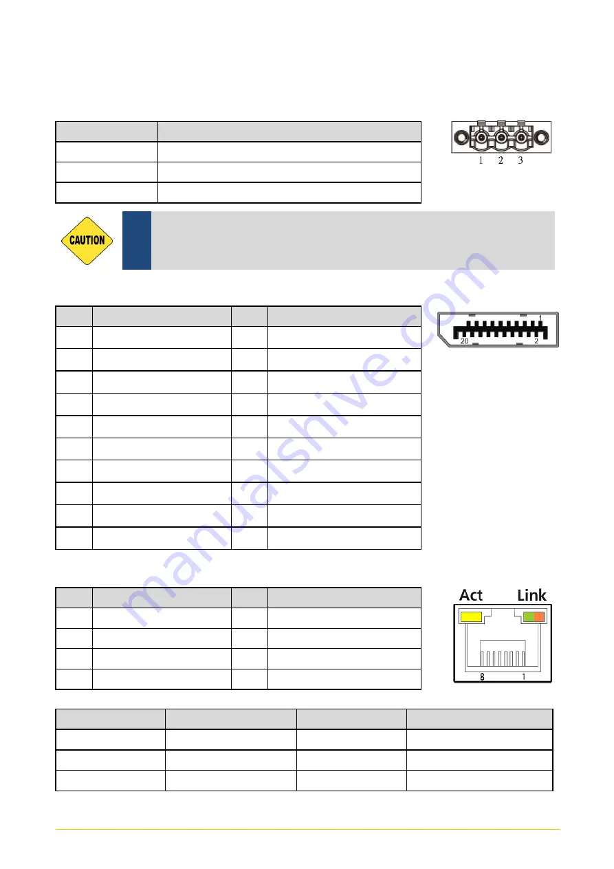
DC_IN1: DC Power Input Connector (+9-48V)
Connector Type: Terminal Block 1X3 3-pin, 5.0mm pitch
Pin
Definition
1
+9-48VIN
2
Chassis GND
3
GND
DP1: DisplayPort Connector
Pin
Definition
Pin
Definition
1
DP_LANE0_P
11
GND
2
GND
12
DP_LANE3_N
3
DP_LANE0_N
13
GND
4
DP_LANE1_P
14
GND
5
GND
15
DP_AUX_P
6
DP_LANE1_N
16
GND
7
DP_LANE2_P
17
DP_AUX_N
8
GND
18
DP_HPD
9
DP_LANE2_N
19
GND
10
DP_LANE3_P
20
DP_PWR
LAN1/LAN2: RJ45 with LEDs Port
Pin
Definition
Pin
Definition
1
LAN_MDI0P
5
LAN_MDI2N
2
LAN_MDI0N
6
LAN_MDI1N
3
LAN_MDI1P
7
LAN_MDI3P
4
LAN_MDI2P
8
LAN_MDI3N
Act LED Status
Definition
Link LED Status Definition
Blinking Yellow
Data Activity
Steady Green
1Gbps Network Link
Off
No Activity
Steady Orange
100Mbps Network Link
Off
10Mbps Network Link
Please disconnect the power source before mounting the DC
power cables or connecting the DC power connector to system.
CAUT
IO
N
Summary of Contents for CO-100/P1001 Series
Page 11: ...CO 100 P1001 Series User Manual 11 Chapter 1 Product Introductions ...
Page 17: ...CO 100 P1001 Series User Manual 17 Dimension CO W121C P1001 Unit mm CO W121C P1001E Unit mm ...
Page 20: ...CO 100 P1001 Series User Manual 20 Chapter 2 Jumpers Switches Connectors ...
Page 22: ...CO 100 P1001 Series User Manual 22 2 2 2 Bottom View ...
Page 31: ...CO 100 P1001 Series User Manual 31 Chapter 3 System Setup ...
Page 53: ...CO 100 P1001 Series User Manual 53 Chapter 4 BIOS Setup ...
Page 72: ...CO 100 P1001 Series User Manual 72 Chapter 5 Product Application ...
Page 80: ...CO 100 P1001 Series User Manual 80 ...
Page 81: ...CO 100 P1001 Series User Manual 81 Chapter 6 Optional Accessories ...


