CO
-
100/P1001
Series | User Manual
27
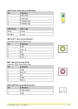
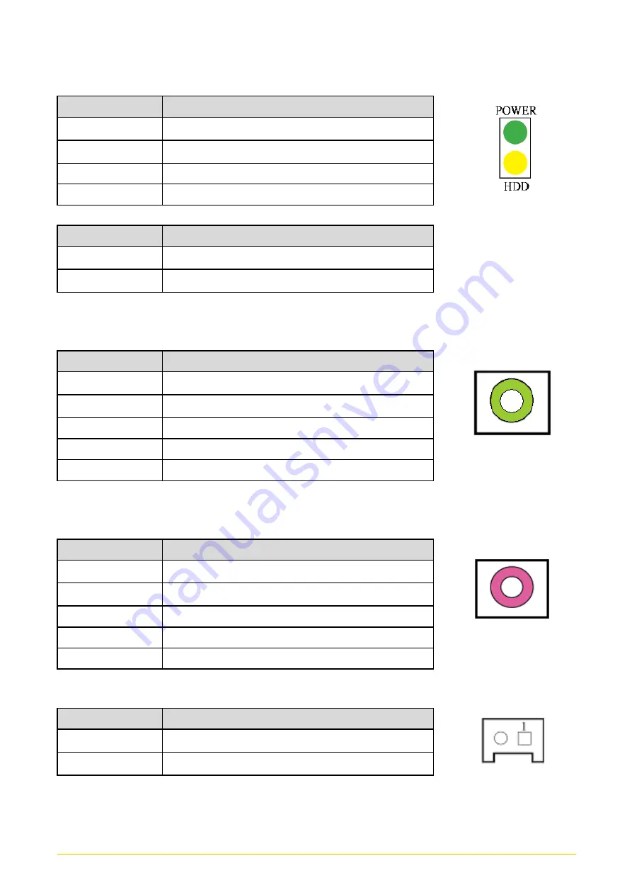
LED1: Power / HDD Access LED Status
Pin
Definition
1
HDD LED+
2
HDD LED-
3
POWER LED+
4
POWER LED-
LED Status
LED Color
HDD
Yellow
POWER
Green
LINE_OUT1: Line-out Jack (Green)
Connector Type: 5-pin Phone Jack
Pin
Definition
1
GND
2
OUT_R
3
NC
4
GND
5
OUT_L
MIC1: Microphone Jack (Pink)
Connector Type: 5-pin Phone Jack
Pin
Definition
1
GND
2
MIC_R
3
NC
4
GND
5
MIC_L
PWR_SW1
:
Power Switch Connector
Pin
Definition
1
Power switch
2
GND
Summary of Contents for CO-100/P1001 Series
Page 11: ...CO 100 P1001 Series User Manual 11 Chapter 1 Product Introductions ...
Page 17: ...CO 100 P1001 Series User Manual 17 Dimension CO W121C P1001 Unit mm CO W121C P1001E Unit mm ...
Page 20: ...CO 100 P1001 Series User Manual 20 Chapter 2 Jumpers Switches Connectors ...
Page 22: ...CO 100 P1001 Series User Manual 22 2 2 2 Bottom View ...
Page 31: ...CO 100 P1001 Series User Manual 31 Chapter 3 System Setup ...
Page 53: ...CO 100 P1001 Series User Manual 53 Chapter 4 BIOS Setup ...
Page 72: ...CO 100 P1001 Series User Manual 72 Chapter 5 Product Application ...
Page 80: ...CO 100 P1001 Series User Manual 80 ...
Page 81: ...CO 100 P1001 Series User Manual 81 Chapter 6 Optional Accessories ...


