CO
-
100/P1001
Series | User Manual
82
6.1
Installing VESA Mount
Before the installation of VESA mount, user need to follow the chapter 3.13 to disassemble
the mounting brackets on the CO display module first.
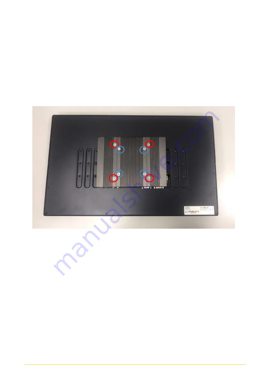
P1000 series supports VESA mounting that customer can mount system with panel
complying with VESA 75mm and 100 mm standard for various usage. The 75mm VESA
uses blue-circle-marked screw holes.
The 100mm VESA uses red-circle-marked screw
holes.
1.
Put the VESA stand on, and align with the mounting holes.
Summary of Contents for CO-100/P1001 Series
Page 11: ...CO 100 P1001 Series User Manual 11 Chapter 1 Product Introductions ...
Page 17: ...CO 100 P1001 Series User Manual 17 Dimension CO W121C P1001 Unit mm CO W121C P1001E Unit mm ...
Page 20: ...CO 100 P1001 Series User Manual 20 Chapter 2 Jumpers Switches Connectors ...
Page 22: ...CO 100 P1001 Series User Manual 22 2 2 2 Bottom View ...
Page 31: ...CO 100 P1001 Series User Manual 31 Chapter 3 System Setup ...
Page 53: ...CO 100 P1001 Series User Manual 53 Chapter 4 BIOS Setup ...
Page 72: ...CO 100 P1001 Series User Manual 72 Chapter 5 Product Application ...
Page 80: ...CO 100 P1001 Series User Manual 80 ...
Page 81: ...CO 100 P1001 Series User Manual 81 Chapter 6 Optional Accessories ...


