CV
-
100/
P1100 Series | User Manual
117
6.1 Location of the Connectors and Switches
Model No.
Description
CFM-IGN101
CFM Module with Power Ignition Sensing Control Function,
12V/24V Selectable
CFM-PoE02
CFM Module with PoE Control Function, Individual Port 25.5W
6.2
Installing a CFM-IGN Module
1.
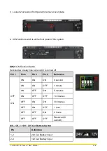
Locate the IGN connector on system motherboard as indicated.
2.
Insert CFM-IGN module vertically to the female connector on the system’s mainboard,
and fasten 2 screws to fix it.
Summary of Contents for CV-100/P1100 Series
Page 15: ...CV 100 P1100 Series User Manual 15 Chapter 1 Product Introductions ...
Page 21: ...CV 100 P1100 Series User Manual 21 Dimension CV 108 P1101 Unit mm ...
Page 25: ...CV 100 P1100 Series User Manual 25 Dimension CV 110 P1101 Unit mm ...
Page 29: ...CV 100 P1100 Series User Manual 29 Dimension CV 110H P1101 Unit mm ...
Page 33: ...CV 100 P1100 Series User Manual 33 Dimension CV 112H P1101 Unit mm ...
Page 37: ...CV 100 P1100 Series User Manual 37 Dimension CV 115 P1101 Unit mm ...
Page 41: ...CV 100 P1100 Series User Manual 41 Dimension CV W115 P1101 Unit mm ...
Page 45: ...CV 100 P1100 Series User Manual 45 Dimension CV 117 P1101 Unit mm ...
Page 49: ...CV 100 P1100 Series User Manual 49 Dimension CV 119 P1101 Unit mm ...
Page 53: ...CV 100 P1100 Series User Manual 53 Dimension CV W121 P1101 Unit mm ...
Page 57: ...CV 100 P1100 Series User Manual 57 Dimension CV W124 P1101 Unit mm ...
Page 61: ...CV 100 P1100 Series User Manual 61 Chapter 2 Switches Connectors ...
Page 62: ...CV 100 P1100 Series User Manual 62 2 1 Location of Switches and Connectors 2 1 1 Top View ...
Page 63: ...CV 100 P1100 Series User Manual 63 2 1 2 Bottom View ...
Page 71: ...CV 100 P1100 Series User Manual 71 Chapter 3 System Setup ...
Page 87: ...CV 100 P1100 Series User Manual 87 ...
Page 89: ...CV 100 P1100 Series User Manual 89 Chapter 4 BIOS Setup ...
Page 107: ...CV 100 P1100 Series User Manual 107 Chapter 5 Product Application ...

