CV
-
100/
P1100 Series | User Manual
120
4.
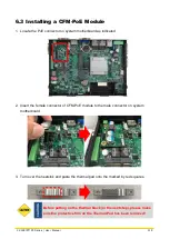
Paste the heatsink onto the CFM-PoE module carefully and fasten 2 screws to fix it.
5.
Paste the thermal pads onto the heatsink and coil carefully.
6.
When the system is power on, please note that the POE LED will light on if the POE
module is properly installed.
Before assembling the system’s chassis cover, please make sure
the protective films on the Thermal Pads have been removed!
CAUT
IO
N
Summary of Contents for CV-100/P1100 Series
Page 15: ...CV 100 P1100 Series User Manual 15 Chapter 1 Product Introductions ...
Page 21: ...CV 100 P1100 Series User Manual 21 Dimension CV 108 P1101 Unit mm ...
Page 25: ...CV 100 P1100 Series User Manual 25 Dimension CV 110 P1101 Unit mm ...
Page 29: ...CV 100 P1100 Series User Manual 29 Dimension CV 110H P1101 Unit mm ...
Page 33: ...CV 100 P1100 Series User Manual 33 Dimension CV 112H P1101 Unit mm ...
Page 37: ...CV 100 P1100 Series User Manual 37 Dimension CV 115 P1101 Unit mm ...
Page 41: ...CV 100 P1100 Series User Manual 41 Dimension CV W115 P1101 Unit mm ...
Page 45: ...CV 100 P1100 Series User Manual 45 Dimension CV 117 P1101 Unit mm ...
Page 49: ...CV 100 P1100 Series User Manual 49 Dimension CV 119 P1101 Unit mm ...
Page 53: ...CV 100 P1100 Series User Manual 53 Dimension CV W121 P1101 Unit mm ...
Page 57: ...CV 100 P1100 Series User Manual 57 Dimension CV W124 P1101 Unit mm ...
Page 61: ...CV 100 P1100 Series User Manual 61 Chapter 2 Switches Connectors ...
Page 62: ...CV 100 P1100 Series User Manual 62 2 1 Location of Switches and Connectors 2 1 1 Top View ...
Page 63: ...CV 100 P1100 Series User Manual 63 2 1 2 Bottom View ...
Page 71: ...CV 100 P1100 Series User Manual 71 Chapter 3 System Setup ...
Page 87: ...CV 100 P1100 Series User Manual 87 ...
Page 89: ...CV 100 P1100 Series User Manual 89 Chapter 4 BIOS Setup ...
Page 107: ...CV 100 P1100 Series User Manual 107 Chapter 5 Product Application ...


